Iron nail attracting equipment for building construction protection

A technology for building construction and iron nails, which is applied in the field of iron-absorbing nail equipment, and can solve problems such as difficult removal of iron nails and iron removal

Active Publication Date: 2020-12-25
徐小兵
View PDF6 Cites 0 Cited by
  • Summary
  • Abstract
  • Description
  • Claims
  • Application Information

AI Technical Summary

Problems solved by technology

[0005] In order to overcome the disadvantages that it is not easy to take out the iron nails and the iron needs to be removed manually when collecting iron nails, the technical problem is to provide a kind of absorbing iron for building construction protection that is easy to collect iron nails, does not need to be manually removed by hand, and is easy to move Nail equipment

Method used


Image

  • Iron nail attracting equipment for building construction protection
  • Iron nail attracting equipment for building construction protection
  • Iron nail attracting equipment for building construction protection

Examples


Embodiment 1

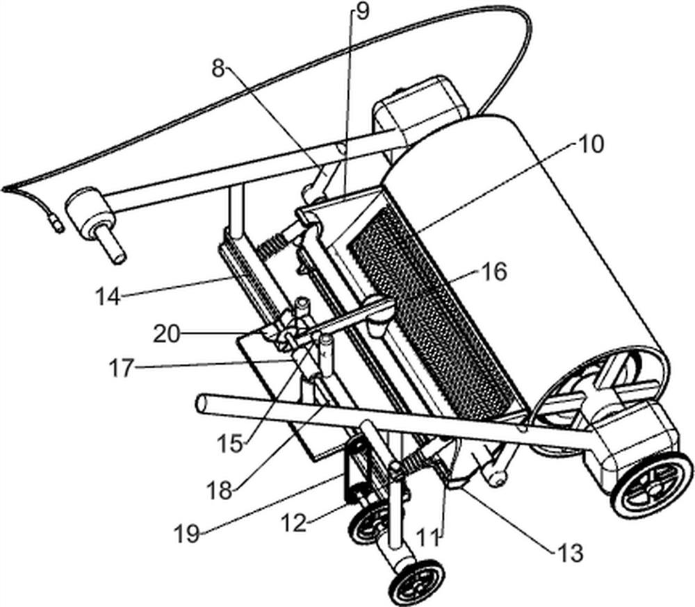
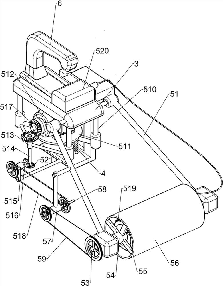
[0022] A kind of suction nail equipment for building construction protection, such as figure 1 , figure 2 with image 3 , including a frame 1, a first slider 2, a mounting frame 3, a first elastic member 4, an iron-absorbing mechanism 5, a handle 6 and a fixing mechanism 7, and the left side of the frame 1 is provided with a first slider in a sliding manner 2. A mounting frame 3 is fixedly connected to the first slider 2, and a first elastic member 4 is symmetrically connected front and rear between the first slider 2 and the frame 1. The first elastic member 4 is a compression spring, and the mounting frame 3 An iron-absorbing mechanism 5 is arranged on the top, a handle 6 is arranged on the rear side of the top of the mounting frame 3, and a fixing mechanism 7 is arranged on the right side of the frame 1.

[0023] When people need to use this device, first people put the fixing mechanism 7 on their body, at this moment, due to the effect of gravity, the iron-absorbing mec...

Embodiment 2

[0029] On the basis of Example 1, such as Figure 4 with 5 As shown, it also includes a fifth connecting rod 8, a collection frame 9, a screen 10, a second slide block 12, a movable block 13, a second fixed block 14, an H-shaped bar 15, a rotating block 16, and a first guide sleeve 17 , the second rotating rod 18, the third belt transmission device 19 and the rotary dial 20, the bottom of the first connecting rod 51 is fixedly connected with the fifth connecting rod 8, and the fifth connecting rod 8 is provided with a collection frame in a rotating manner 9. The collection frame 9 is in contact with the sleeve 56. The bottom of the collection frame 9 has a discharge port, the front side of the collection frame 9 is provided with a screen 10, and the lower part of the collection frame 9 is symmetrically provided with a chute 11 front and rear. A plurality of second sliders 12 are slidingly arranged on the groove 11, and the quantity of the second sliders 12 is 4. A movable blo...


PUM


Abstract

The invention relates to iron nail attracting equipment, in particular to iron nail attracting equipment for building construction protection. According to the iron nail attracting equipment for building construction protection, iron nails can be collected conveniently, the iron nails do not need to be taken down manually, and moving is convenient. The iron nail attracting equipment for building construction protection comprises a rack, a mounting frame, first elastic parts, an iron attracting mechanism, a handle and a fixing mechanism, wherein a first sliding block is arranged on the rack ina sliding mode; the mounting frame is arranged on the first sliding block; the first elastic parts are symmetrically connected between the first sliding block and the rack; the iron attracting mechanism is arranged on the mounting frame; the handle is arranged on the mounting frame; and the fixing mechanism is arranged on the side, away from the first sliding block, of the rack. The equipment is worn on the body of a user through the fixing mechanism to be driven to move freely, then a servo motor and a storage battery are started to enable a sleeve to rotate and enable an electrified coil togenerate magnetic force, then iron nails and other small iron parts are attracted to the sleeve, and therefore convenience is provided for people.

Description

technical field [0001] The invention relates to an iron-absorbing nail device, in particular to an iron-absorbing nail device for building construction protection. Background technique [0002] Iron nails, one end is flat and the other end is sharp, are mainly used for fixing or connecting. Iron nails are often used on construction sites, so iron nails are often dropped on construction sites, and workers will be caught on the ground if they are not careful. In order to prevent the occurrence of safety accidents, the nails need to be collected. [0003] At present, most of the iron nails on the ground are manually picked up by people, and this collection method is not only time-consuming and labor-intensive, but also the iron nails hidden in the sundries are usually difficult for workers to find and pick up, while the existing iron nails Although the equipment can pick up small iron parts such as iron nails, it is not easy to take out the iron nails during operation, and the...

Claims


Application Information

Patent Timeline
Patent Type & Authority Applications(China)
IPC IPC(8): E01H1/14E04G21/32
CPCE01H1/14E04G21/32
Inventor 陈春艳
Owner 徐小兵
Why Eureka
Try Eureka