Intelligent lock based on micro-energy power supply

An intelligent lock and micro-energy technology, applied in the field of locks, can solve the problems of inability to achieve the unlocking experience of traditional locks, inability to be promoted and applied, and insufficient unlocking power, so as to improve the unlocking response and user experience, reduce the lock specific volume, and reduce energy. desired effect

Pending Publication Date: 2020-12-25
广东平方科技有限公司
View PDF0 Cites 0 Cited by
  • Summary
  • Abstract
  • Description
  • Claims
  • Application Information

AI Technical Summary

Problems solved by technology

The current low-power ordinary smart locks have certain limitations in the design of the unlocking reliability structure, especially for passive IoT smart locks, because the energy is weak and the unlocking torque is too small, resulting in a short unlocking stroke and insufficient unlocking force, it cannot be obtained Good promotion and application, compared with common external or built-in power supply smart locks, there is still a considerable gap in promotion
[0004] Specifically, there are mainly the following problems: 1. Traditional mechanical or active locks can easily overcome the elastic force + friction force generated by the compression spring of the lock pin to achieve the purpose of unlocking, while passive or micro-energy locks cannot be unlocked according to conventional methods due to insufficient energy supply. The design is easy to cause insufficient unlocking torque
2. When unlocking, passive locks need to obtain and store energy from the environment, and the unlocking experience is poor after a long time, and cannot achieve the unlocking experience of traditional locks

Method used


Image

  • Intelligent lock based on micro-energy power supply
  • Intelligent lock based on micro-energy power supply
  • Intelligent lock based on micro-energy power supply

Examples


Embodiment Construction

[0028] The specific implementation of the present invention will be further described below in conjunction with the accompanying drawings. For the convenience of description, the application may define directions such as up, down, left, right, front, back, horizontal, vertical, and axial directions, in order to facilitate Clearly describe the relative positional relationship of the structure, and is not used to limit the actual orientation of the product in the process of production, use, and sales. The specific embodiment of the present invention will be further described below in conjunction with accompanying drawing:

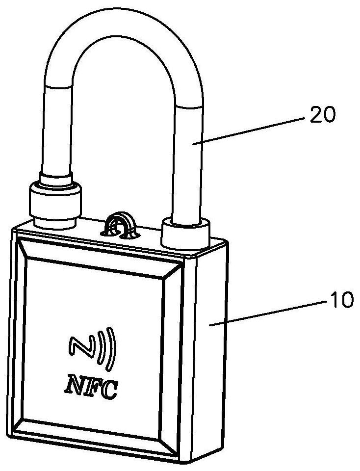
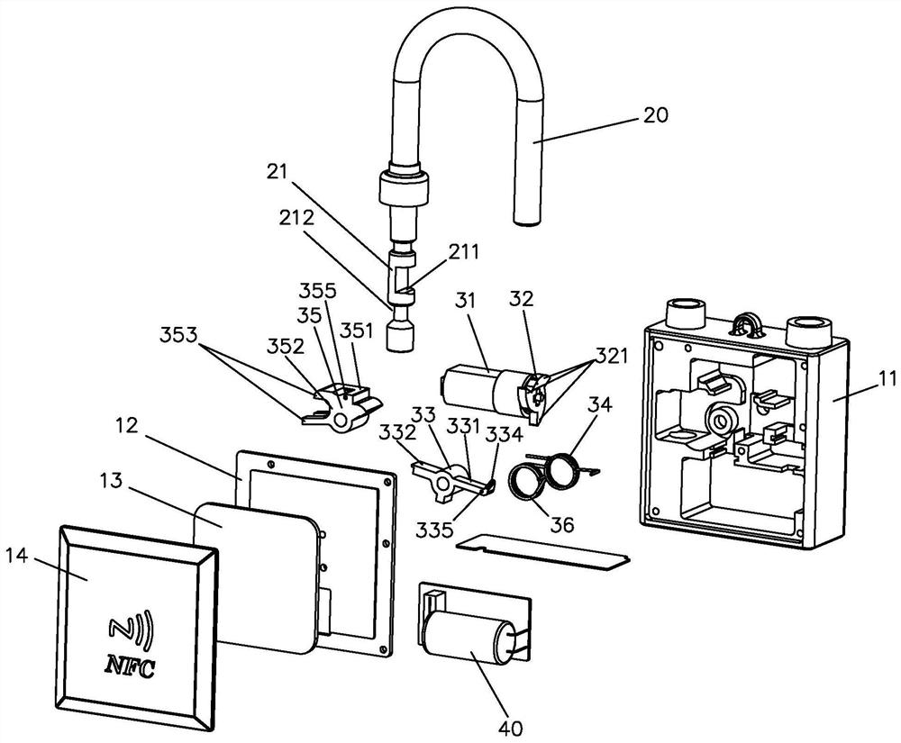
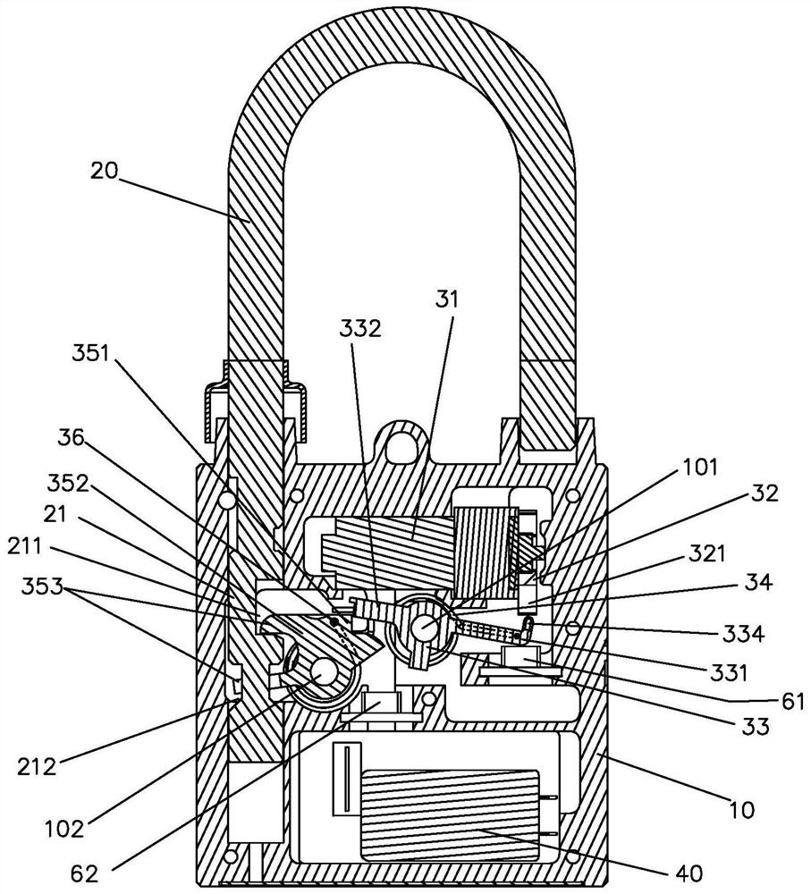
[0029] Such as figure 1 with figure 2 As shown, the smart lock provided in this embodiment includes a lock body 10 , a lock lever 20 , a multi-stage transmission unlocking assembly, and a passive micro-energy module 40 . Wherein, the multi-stage transmission unlocking assembly includes an electric power source 31 , a cam member 32 , a booster lever 33 , a ...


PUM


Abstract

The invention discloses an intelligent lock based on micro-energy power supply. The intelligent lock comprises a lock body and a lock rod, and further comprises a multi-stage transmission unlocking and locking assembly and a passive micro-energy module which are assembled in the lock body, wherein the multi-stage transmission unlocking and locking assembly comprises an electric power source, a campart and at least two stages of lever transmission units; each lever transmission unit comprises a functional lever and an energy storage elastic part; the passive micro-energy module provides a working power source for the electric power source; the cam part is driven by the electric power source to rotate; each lever transmission unit is provided with a trigger end which is driven by the cam part to trigger the corresponding lever transmission unit to swing in a cascading mode; and each lever transmission unit is further provided with a buckle mechanism which locks or releases a locking part when the lever transmission unit swings in the cascading mode. Micro-energy temporarily obtained from the outside can be used as a power supply, and unlocking of the lock is achieved.

Description

technical field [0001] The invention relates to the technical field of locks, in particular to an intelligent lock and a domino drive unlocking mechanism based on micro-energy power supply. Background technique [0002] Smart locks are often used as lock control applications for safety and process control, and their application fields are very wide, for example, lock control for power supply boxes for key urban public facilities, outdoor power distribution cabinets for distribution networks, substation mechanism boxes, and power metering boxes; And, it is used for the lock control of logistics packaging, compartments, and containers; also, it is used for the lock control of oil and gas pipeline valves for material management, and confidential containers for commercial coal samples. [0003] The Internet of Things smart lock based on passive micro-energy power supply technology has obvious advantages and characteristics in industrial application environments where power suppl...

Claims


Application Information

Patent Timeline
Patent Type & Authority Applications(China)
IPC IPC(8): E05B47/00E05B67/00E05B67/06H02J50/10
CPCE05B47/0012E05B67/00E05B67/06E05B2047/0018E05B2047/0024E05B2047/0057E05B2047/0067H02J50/10
Inventor 汪平闵雄卢良斌
Owner 广东平方科技有限公司
Why Eureka
Try Eureka