Multifunctional test bench for chip

A multi-functional test and test bench technology, applied in short-circuit test, electronic circuit test, measurement of electricity, etc., can solve the problems of chip false test, insufficient pressure, test head jitter, etc., to prevent false test and prevent insufficient pressure. , the effect of reducing downward pressure

Pending Publication Date: 2020-12-25
复汉海志(江苏)科技有限公司
View PDF2 Cites 3 Cited by
  • Summary
  • Abstract
  • Description
  • Claims
  • Application Information

AI Technical Summary

Problems solved by technology

The chip test device in the existing published patent CN209606569U has certain disadvantages during use. When the test head moves downward, there is a problem that the pressure exerted by the test head is difficult to grasp, and the loading platform is not equipped with a buffer device, which is easy to produce pressure. If the pressure is too large, or the test head shakes, the chip will be mis-tested, or even the surface of the chip will be split, which will affect the use of subsequent chips. In the chip test platform in the existing patent CN208013370U, the two sides of the box-type platform are equipped with belt The bracket of the longitudinal slideway is equipped with a support plate that can be adjusted up and down. The support plate is fixed with a double-axis cylinder. Although the double-axis cylinder can equalize the pressure generated by the test head in each reciprocating movement, preventing excessive pressure or jittering and mistesting, the overall structure is more complicated, and the output force and torque of the cylinder transmission itself are inconsistent. Large, easy to produce insufficient pressure, low transmission efficiency, and the air is compressible, it is difficult to achieve precise control of the whole device. In addition, after a long time of use, the air cylinder has a risk of sealing and is prone to leakage. The cylinder needs to be maintained regularly. Compared with pure mechanical transmission, it increases the maintenance cost and is not conducive to saving resources.

Method used


Image

  • Multifunctional test bench for chip
  • Multifunctional test bench for chip
  • Multifunctional test bench for chip

Examples


Embodiment 1

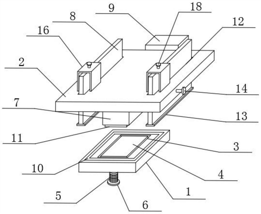
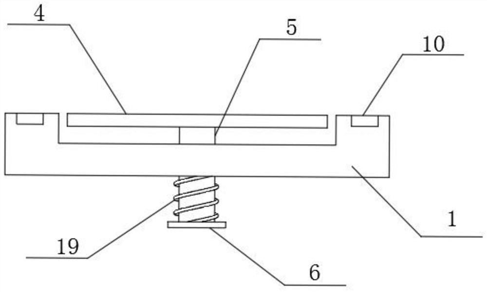
[0024]Such asfigure 1 withimage 3 As shown, a multifunctional chip test bench includes a test bench 1 and a pressing plate 2. A groove 3 is opened in the middle of the top surface of the test bench 1, and a detection board 4 is provided in the groove 3. An inserting rod 5 is provided in the middle of the bottom surface, a connecting ring 6 is provided at the bottom of the inserting rod 5, a connecting block 7 is installed in the middle of the bottom surface of the extrusion plate 2, and the interior of the extrusion plate 2 is set at a limited position near both sides The position plate 8 has a detector 9 mounted on the rear surface of the pressing plate 2.

[0025]The test bench 1 is in the shape of a rectangular parallelepiped. The test bench 1 is provided with a detection board 4 in the middle of the upper surface of the test bench 1, and the groove 3 encloses the detection board 4 in it. The groove 3 is rectangular. On the bottom surface, a washer 10 is embedded in the upper surfac...

Embodiment 2

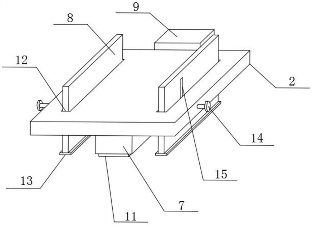
[0027]On the basis of Example 1, such asfigure 2 withFigure 4As shown, both sides of the test bench 1 are provided with grooves 3 for accommodating the limit plates, which can facilitate the relative sliding of the limit plates 8 inside the test bench 1, and the two sides of the connecting block 7 are provided with notches 12. 12 is a long rectangle, the number of notches 12 is two, the limit plate 8 passes through the notch 12, there are two limit plates 8, and the bottom end of the limit plate 8 is equipped with a contact plate 13, the contact plate There are two 13 in number. When the pressing plate goes down, the contact plate will touch the washer, which can prevent the chip from being fractured. Both sides of the pressing plate 2 are provided with adjusting bolts 14 which pass through the screw holes. 17 passes through the side of the extrusion plate 2 and the slot and is screwed to each other with the limit plate 8. The inner surface of the limit plate 8 on the right side is ...


PUM


Abstract

The invention discloses a multifunctional test bench for a chip. The multifunctional test bench comprises a test bench and an extrusion plate, wherein a groove is formed in the middle of the upper surface of the top of the test bench; a detection plate is arranged in the groove; an insertion rod is arranged in the middle of the bottom surface of the test bench; a connection ring is arranged at thebottom end of the insertion rod; a connection block is mounted in the middle of the bottom surface of the extrusion plate; and limiting plates are arranged at positions, close to two sides, in the extrusion plate; and a detector is mounted on the rear surface of the extrusion plate. According to the multifunctional test bench for the chip, the chip can be limited through the limiting plates, so that the chip is prevented from being cracked by the extrusion plate due to a mechanical error; through springs and the insertion rod, the chip can be separated and taken out from the test bench; and the whole test bench is simple in structure, relatively practical and suitable for popularization.

Description

Technical field[0001]The invention relates to the technical field of chip testing, in particular to a chip multifunctional test bench.Background technique[0002]In recent years, with the rapid development of electronic consumer products, in order to satisfy the young people’s pursuit of novelty, a large number of products with attitude sensor chips have been put on the market, which has not only stimulated the semiconductor design and manufacturing industry Progress has also put forward higher requirements for chip packaging and testing technology. Semiconductor testing includes two stages: CP (CircuitProbe) test and FT (Final Test) test. In the traditional test method, in the IC process, each chip needs to be electrically tested before the final package is completed, so as to exclude defective products into the follow-up Package program. When the chip is tested for electrical properties, the probe is used to directly contact the solder pads on the chip for needle testing. The chip t...

Claims


Application Information

Patent Timeline
Patent Type & Authority Applications(China)
IPC IPC(8): G01R31/28G01R1/04G01R31/52
CPCG01R31/2886G01R31/2891G01R31/52
Inventor 任晓伟
Owner 复汉海志(江苏)科技有限公司
Why Eureka
Try Eureka