
Permanent magnet eddy current coupling

A permanent magnet eddy current and coupling technology, applied in the direction of permanent magnet clutch/brake, electric brake/clutch, asynchronous inductive clutch/brake, etc. The effect of torque transmission capacity, low space requirement and flexible layout

Pending Publication Date: 2020-12-25
中国船舶重工集团公司第七0三研究所
View PDF0 Cites 0 Cited by
  • Summary
  • Abstract
  • Description
  • Claims
  • Application Information

AI Technical Summary

Problems solved by technology

[0004] The purpose of the present invention is to solve the problems of small torsion transmission capacity and limited installation in the existing permanent magnet eddy current coupling, in order to further improve the magnetic circuit optimization space of the coupling, a permanent magnet eddy current coupling is provided

Method used


Image

  • Permanent magnet eddy current coupling
  • Permanent magnet eddy current coupling
  • Permanent magnet eddy current coupling

Examples


specific Embodiment approach 1

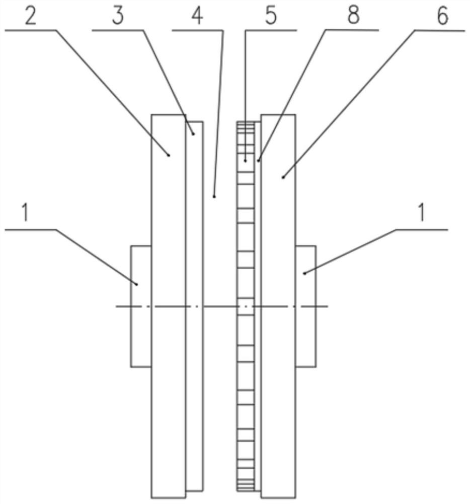
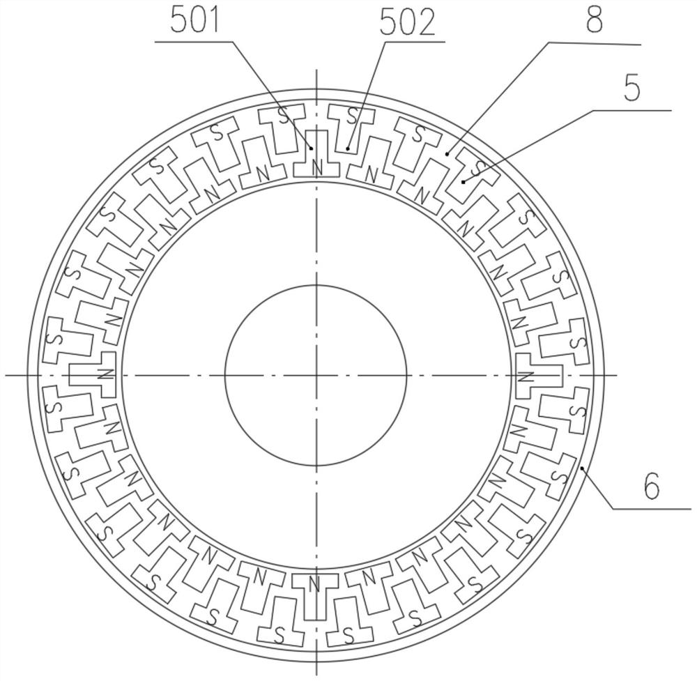
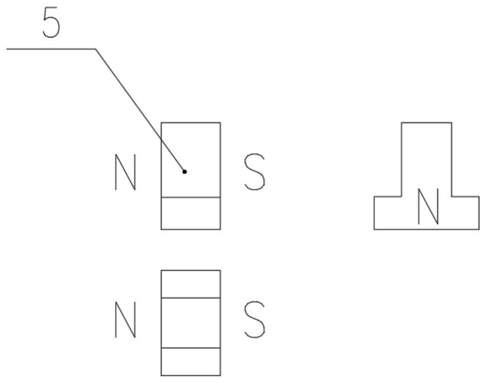
[0023] Specific implementation mode one: the following combination Figure 1 to Figure 3 Describe this embodiment, a permanent magnet eddy current coupling described in this embodiment, which includes a conductor unit and a permanent magnet unit, the conductor unit and the permanent magnet unit are arranged coaxially, with an air gap in the middle;

[0024] The conductor unit includes a conductor back iron plate 2 and a conductor plate 3; the permanent magnet unit includes a permanent magnet 5, a permanent magnet back iron plate 6 and a permanent magnet mounting plate 8;

[0025] The conductor disk 3 is coaxially connected to the conductor back iron disk 2, and the conductor disk 3 is located on the air gap side;

[0026] The permanent magnet mounting plate 8 is coaxially connected with the permanent magnet back iron plate 6, and the permanent magnet mounting plate 8 is located on the air gap side;

[0027] The permanent magnets 5 are arranged at equal intervals along the cir...


PUM


Abstract

A permanent magnet eddy current coupling belongs to the field of magnetic transmission and particularly relates to the field of permanent magnet eddy current couplings. The permanent magnet eddy current coupling solves the problems that an existing permanent magnet eddy current coupling is small in torque transmission capacity and limited in installation. The permanent magnet eddy current couplingcomprises a conductor unit and a permanent magnet unit which are coaxially arranged, and an air gap is formed between the conductor unit and the permanent magnet unit; and each conductor unit comprises a conductor back iron disc and a conductor disc. The permanent magnet unit comprises a permanent magnet, a permanent magnet back iron disc and a permanent magnet mounting disc; the conductor disc is coaxially connected with the back iron disc, and the conductor disc is located at the air gap side; the permanent magnet mounting disc and the permanent magnet back iron disc are coaxially connected, and the permanent magnet mounting disc is located on the air gap side; the permanent magnets are arranged at equal intervals in the circumferential direction of the permanent magnet mounting disc; and the permanent magnets comprise an inner arc permanent magnet and an outer arc permanent magnet, the inner arc permanent magnet and the outer arc permanent magnet are both T-shaped, and the T-shapedhorizontal sections of the inner arc permanent magnet and the outer arc permanent magnet are close to the edge of the permanent magnet mounting disc. The permanent magnet eddy current coupling is suitable for being used as a coupling.

Description

technical field [0001] The invention belongs to the field of magnetic transmission, in particular to the field of permanent magnet eddy current couplings. Background technique [0002] As a connecting device in a mechanical system, the coupling has a wide range of applications. At present, the couplings used in the mechanical field are divided into mechanical couplings, hydraulic couplings and magnetic transmission couplings. The mechanical coupling transmits torque through mechanical connection, the additional force generated during operation is relatively large, and the ability to isolate vibration is relatively weak. The hydraulic coupling transmits torque through the interaction between fluids, the transmission efficiency is reduced, the service life is short, and the later maintenance workload is large. The magnetic transmission coupling uses the interaction between magnetic fields to transmit torque, which belongs to non-contact torque transmission. It has the charac...

Claims


Application Information

Patent Timeline
Patent Type & Authority Applications(China)
IPC IPC(8): H02K49/04H02K49/10
CPCH02K49/046H02K49/108
Inventor 陈克鑫战庆欣曲胜楠
Owner 中国船舶重工集团公司第七0三研究所
Learn More