Petroleum pipe cleaning device

A technology for cleaning devices and oil pipelines, which is applied in the direction of cleaning hollow objects, cleaning methods and utensils, chemical instruments and methods, etc., and can solve tedious and time-consuming problems

Pending Publication Date: 2020-12-29
SOUTHWEST PETROLEUM UNIV
View PDF1 Cites 0 Cited by
  • Summary
  • Abstract
  • Description
  • Claims
  • Application Information

AI Technical Summary

Problems solved by technology

This device can clean pipes with various diameters and has high efficiency. However, in order to adapt to different pipe diameters, the cleaning block is compressed by a spring and then clings to the pipe wall. Therefore, when it is inserted into the pipe, it is necessary to manually compr

Method used


Image

  • Petroleum pipe cleaning device
  • Petroleum pipe cleaning device
  • Petroleum pipe cleaning device

Examples


Embodiment

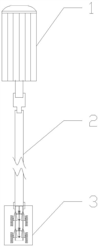
[0018] An oil pipeline cleaning device, such as figure 1 , including a motor 1 and a rotating rod 2, one end of the rotating rod 2 is connected with the rotor of the motor 1, and the other end is connected with the cleaning structure 3.

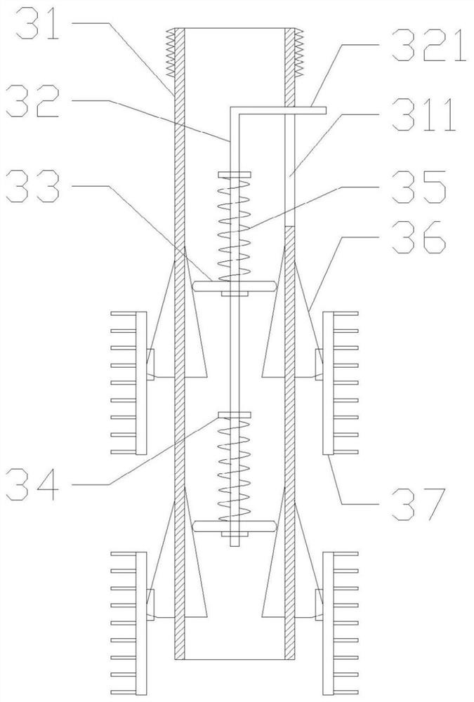
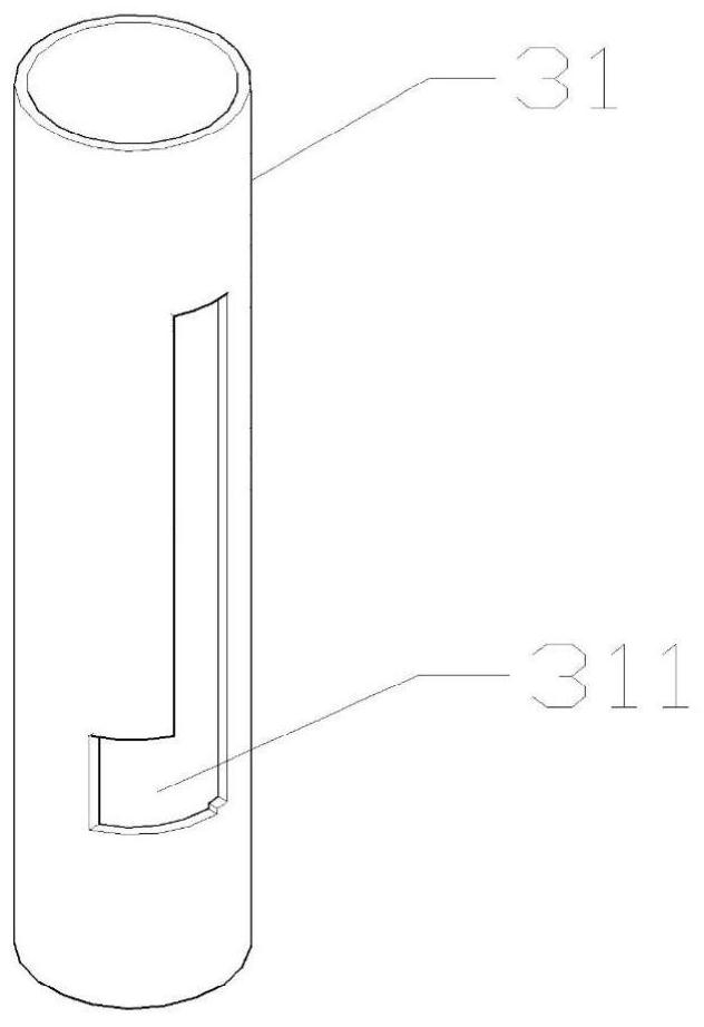
[0019] Such as figure 2 with image 3 , the cleaning structure includes a cylinder body 31 and two cleaning assemblies, each cleaning assembly includes a push rod 32, a disc 33, a stop ring 34, an elastic element 35, a trapezoidal block 36, and a cleaning head 37; the push rod 32 is located in the barrel In the body 31, the disc 33 is movably socketed on the push rod 32, and the limit ring 34 is arranged on the push rod 32, above and below the disc 33, so that the disc 33 can only move within a certain range along the push rod 32. Longitudinal movement inside, an elastic element 35 is set between the disc 34 and the stop ring 34 above it; the trapezoidal block 36 runs through the side wall of the cylinder 31 and faces the position of the d...


PUM


Abstract

The invention discloses a petroleum pipe cleaning device, and belongs to the technical field of pipe cleaning. The device comprises a motor and a rotating rod, wherein one end of the rotating rod is connected with a rotor of the motor, and the other end of the rotating rod is connected with a cleaning structure; the cleaning structure comprises a cylinder, a push rod is arranged in the cylinder, discs are arranged on the push rod, and the push rod is used for driving the discs to move axially along the cylinder; and trapezoid blocks are arranged on the side wall of the cylinder and right facethe discs, the trapezoid blocks have narrow tops and wide bottoms, bodies of the trapezoid blocks penetrate through the side wall of the cylinder, the upper ends of the trapezoid blocks are hinged tothe cylinder, and cleaning heads are hinged to the sides, outside the cylinder, of the lower ends of the trapezoid blocks. According to the device, the trapezoidal blocks and the cleaning heads can betightly attached to the outer wall of the cylinder under the action of gravity, the device can be conveniently placed in a pipe, the push rod drives the discs to move downwards to extrude the trapezoidal blocks, the trapezoidal blocks can rotate, and then the cleaning heads are moved to be tightly attached to the pipe wall, so that the device is convenient to use and saves time.

Description

technical field [0001] The invention relates to the technical field of pipeline cleaning, in particular to an oil pipeline cleaning device. Background technique [0002] The pipeline is a kind of fluid conveying equipment. During actual operation, due to the corrosiveness of the fluid and the inclusion of impurities, the inner wall of the pipeline will gradually scale, resulting in an increase in the friction coefficient of the inner wall of the pipeline, a decrease in the flow channel area, and an increase in transportation consumption. Power, such as oil pipelines, will gradually deposit a certain thickness of paraffin, colloid, condensate, sand and other impurities on the inner wall of the pipeline, collectively known as wax deposition. Paraffin wax has accumulated on the inner wall of the oil pipeline for a long time, which affects the transportation capacity of the oil pipeline. For large-scale equipment, it is usually cleaned by supporting cleaning balls and other equi...

Claims


Application Information

Patent Timeline
IPC IPC(8): B08B9/047
CPCB08B9/0436
Inventor 史亚洲陈利琼
Owner SOUTHWEST PETROLEUM UNIV
Why Eureka
Try Eureka