Deep foundation pit protective fence and protective fence mounting method

A technology for guardrails and deep foundation pits, which can be used in fencing, excavation, infrastructure engineering, etc., and can solve problems such as poor installation quality of guardrails

Inactive Publication Date: 2020-12-29
CHINA FIRST METALLURGICAL GROUP
View PDF8 Cites 1 Cited by
  • Summary
  • Abstract
  • Description
  • Claims
  • Application Information

AI Technical Summary

Problems solved by technology

[0003] One of the purposes of this application is to provide a deep foundation pit guardrail and a guardrail installation method, aiming to improve the poor installation quality of the guardrail on the existing crown beam

Method used


Image

  • Deep foundation pit protective fence and protective fence mounting method
  • Deep foundation pit protective fence and protective fence mounting method
  • Deep foundation pit protective fence and protective fence mounting method

Examples


no. 1 example

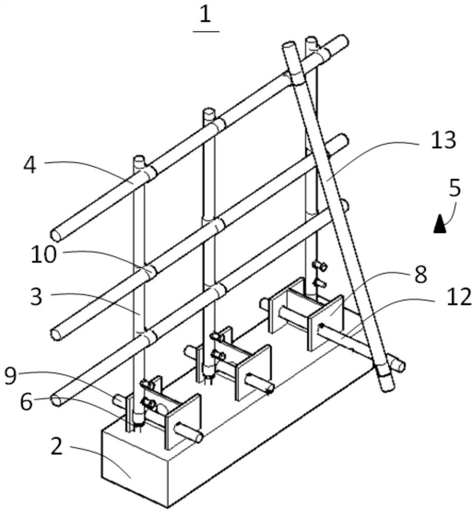
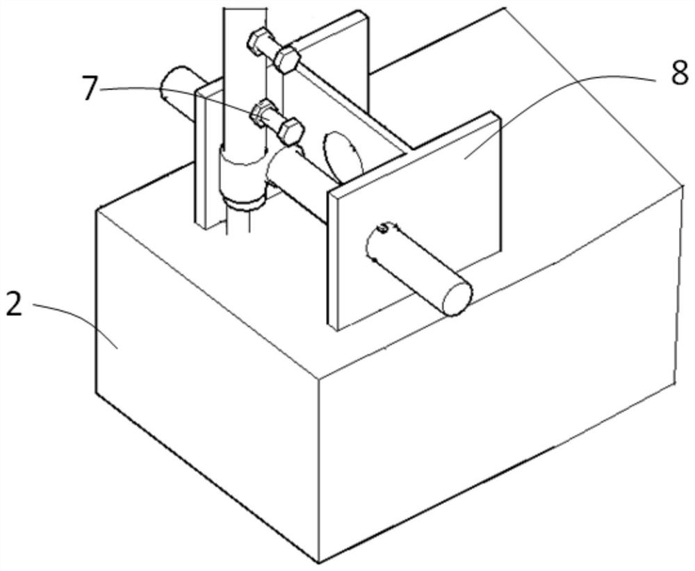
[0036] Please refer to figure 1 , with reference to figure 2 , the application provides a deep foundation pit protection fence, which is suitable for the situation that the pre-embedded steel bar 6 is relatively close to the H-shaped steel 8 of the crown beam 2; The pre-embedded steel bars 6 are embedded in parallel at intervals, and the pre-embedded steel bars 6 are buried in the concrete of the crown beam 2 by 200 mm, and the exposed 400 mm; the bottom ends of a plurality of vertical steel pipes 3 are fixedly socketed on the top of the pre-embedded steel bars 6 through bolts 7; A plurality of horizontal bars 4 are fixedly installed on a plurality of vertical steel pipes 3 in parallel and at intervals, and are arranged at intervals along the height direction of the vertical steel pipes 3. on a vertical steel pipe 3; a plurality of fixed structures 5 are fixedly installed on the crown beam 2 at intervals, and are fixedly connected to the corresponding vertical steel pipes 3 ...

no. 2 example

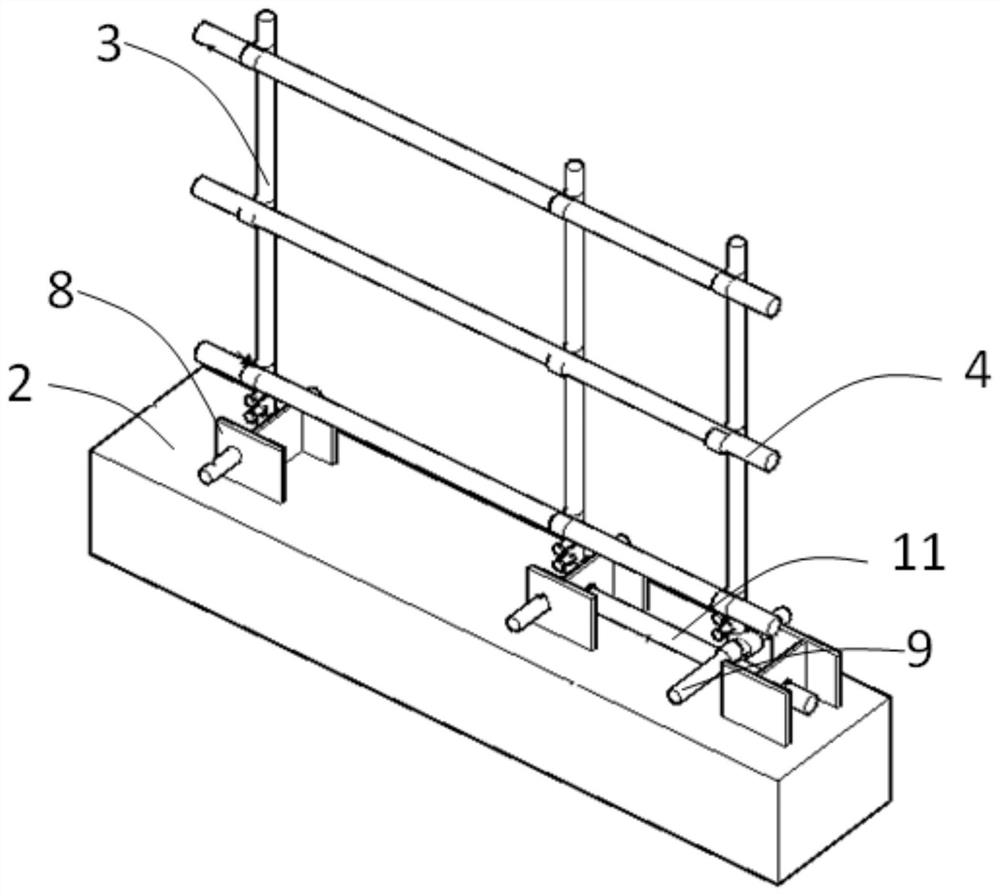
[0049] Please refer to image 3 , the application provides a deep foundation pit protection fence, which is mainly applicable to the situation where the distance between the H-shaped steel 8 and the embedded steel bar 6 is far away. The deep foundation pit protection fence in this embodiment is roughly the same as that in the first embodiment. The difference is that the connection between the fixed structure 5 and the vertical steel pipe 3 is different.

[0050] Further, in this embodiment, the fixed structure 5 includes H-shaped steel 8, longitudinal short steel pipe 11 and first transverse short steel pipe 9; ; The web of each H-shaped steel 8 is provided with a corresponding second hoisting hole, and the two ends of the longitudinal short steel pipe 11 respectively pass through two adjacent second hoisting holes, and are fastened to the first hoisting hole by a wooden wedge. Two hoisting holes. At the same time, the middle part of the longitudinal short steel pipe 11 is v...


PUM


Abstract

The invention provides a deep foundation pit protective fence and a protective fence mounting method, and belongs to the field of buildings. The deep foundation pit protective fence comprises a top beam, a plurality of vertical steel pipes, a plurality of horizontal cross rods and a plurality of fixing structures; the multiple vertical steel pipes are fixedly mounted on the upper portion of the top beam in parallel at intervals; the multiple horizontal cross rods are fixedly mounted on the vertical steel pipes in parallel at intervals and are arranged in the height direction of the vertical steel pipes at intervals; and the multiple fixing structures are fixedly mounted on the top beam at intervals and fixedly connected with the corresponding vertical steel pipes. The deep foundation pit protective fence is convenient to mount, fast and convenient to use, high in practicability and capable of effectively improving the mounting quality of the protective fence on the top beam.

Description

technical field [0001] The present application relates to the construction field, in particular to a deep foundation pit protective fence and a method for installing the protective fence. Background technique [0002] In projects such as pipe corridors and subways that need to excavate long strips of deep foundation pits, two layers of protective railings are required for deep foundation pits. The guardrail must be installed firmly and reliably. The outer protective fence can be installed according to the traditional method. The inner protective fence on the crown beam is limited by the H-shaped steel. Whether it is fixed with expansion bolts or welded, it cannot meet the site protection requirements. Due to the limitations of the construction site, welding or During installation, it is necessary to work on the side of the inner layer of the protective fence close to the foundation pit, which poses a great safety hazard and the installation quality cannot be guaranteed. If...

Claims


Application Information

Patent Timeline
Patent Type & Authority Applications(China)
IPC IPC(8): E02D17/04E04H17/14E04H17/22
CPCE02D17/04E04H17/14E04H17/22
Inventor 武云亮魏华杰马新国赵亮陈世伟李岩狄昊齐利涛
Owner CHINA FIRST METALLURGICAL GROUP
Why Eureka
Try Eureka