Mounting method of prefabricated load-bearing wall

An installation method and wall technology, applied in the direction of walls, building materials, building components, etc., can solve the problems of troublesome disassembly and assembly of the formwork structure, substandard verticality, inaccurate positioning, etc., so as to reduce dust and slag. , saving manpower and ensuring the effect of structural safety

Inactive Publication Date: 2020-12-29
成都建工第二建筑工程有限公司
View PDF9 Cites 4 Cited by
  • Summary
  • Abstract
  • Description
  • Claims
  • Application Information

AI Technical Summary

Problems solved by technology

[0008] The main purpose of the present invention is to provide the installation method of prefabricated load-bearing wall, the installation structure of prefabricated load-bearing wall, the installation method of prefabricated non-load-bearing wall and the installation structure of prefabricated non-load-bearing wall, to solve the problem of transition layer and prefabricated components in the prior art There are technical problems such as inaccurate positioning, weak fixation, and substandard verticality in the installation
Another object of the present invention is the cast-in-place joint formwork structure, which solves the technical problems of troublesome disassembly and grout leakage of the existing formwork structure

Method used


Image

  • Mounting method of prefabricated load-bearing wall
  • Mounting method of prefabricated load-bearing wall
  • Mounting method of prefabricated load-bearing wall

Examples


Embodiment 1

[0133] The prefabricated load-bearing wall in this embodiment is a prefabricated load-bearing wall with a length greater than 1m, which is an external wall of a building, and requires caulking and compartments during installation.

[0134] The installation method of the prefabricated load-bearing wall includes the following steps:

[0135] 1) Measuring and setting out

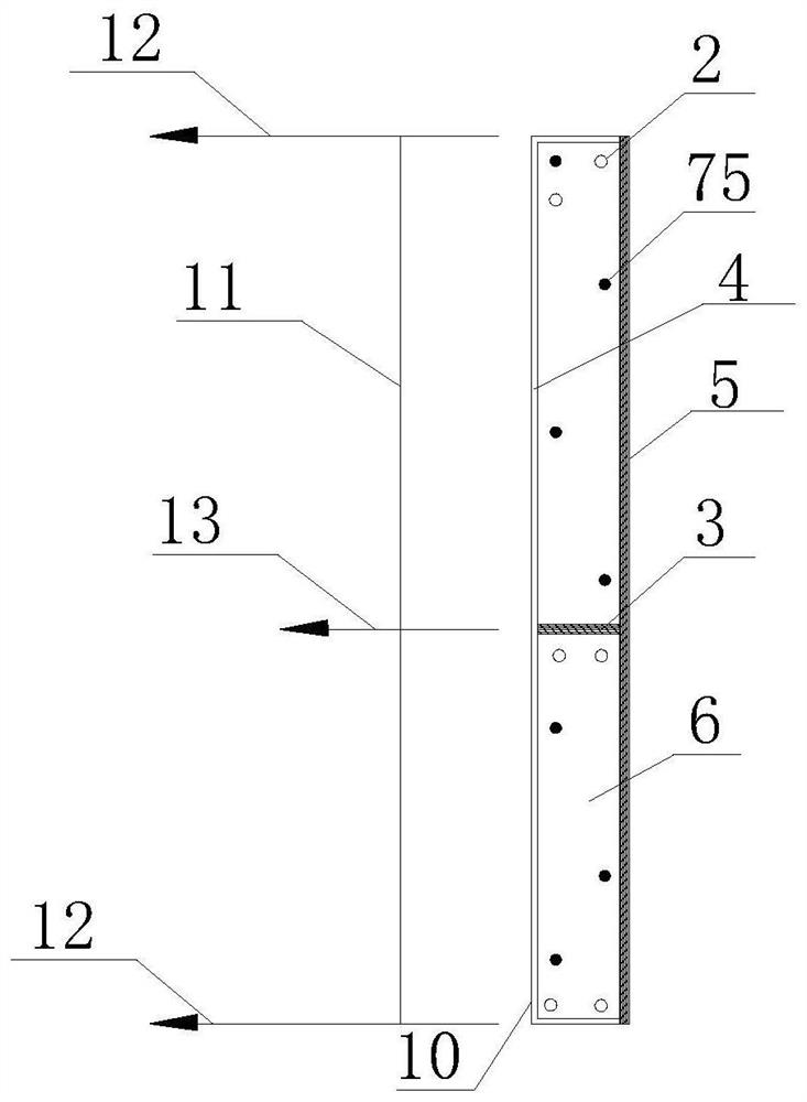
[0136] Such as figure 1 , 4 As shown, pop up the sideline 10 of the bottom surface of the prefabricated load-bearing wall on the installation surface where the prefabricated load-bearing wall is installed, and then move 250mm outside the installation surface to pop up the X-direction control line 11 that is parallel to the bottom sideline 10 of the inner surface and whose length matches. The Y direction control line 12 pops up at both ends of the X direction control line 11;

[0137] 2) Leveling

[0138] Such as Figure 1-3 As shown, six leveling test blocks 2 are used to control the flatness of the instal...

Embodiment 2

[0155] The prefabricated load-bearing wall in this embodiment is a prefabricated load-bearing wall with a length greater than 1m, which is an interior wall of a building. No caulking is required during installation, but separate warehouses are required.

[0156] The installation method of the prefabricated load-bearing wall includes the following steps:

[0157] 1) Measuring and setting out

[0158] Such as Figure 5-6 As shown, pop up the sideline 10 of the bottom surface of the prefabricated load-bearing wall on the installation surface where the prefabricated load-bearing wall is installed, and then move 150mm to the outside of the installation surface to pop up an X-direction control parallel to the bottom sideline 10 of the side with a larger area and matching the length. line 11, popping up the Y-direction control line 12 at both ends of the X-direction control line 11;

[0159] 2) Leveling

[0160] Such as Figure 5-6 As shown, six leveling test blocks 2 are used to...

Embodiment 3

[0175] The prefabricated load-bearing wall in this embodiment is a prefabricated column with a square cross-section and a side length of 1.2m. It is an internal wall of the building. It needs to be divided into warehouses during installation, but no caulking is required.

[0176] The installation method of the prefabricated column comprises the following steps:

[0177] 1) Measuring and setting out

[0178] Such as Figure 7 As shown, the side line 10 of the bottom surface of the prefabricated column pops up on the installation surface where the prefabricated column is installed, and then moves 350 mm outside the installation surface to pop up any X-direction control line 11 that is parallel to the side line 10 and whose length matches. The Y-direction control line 12 pops up at both ends of the control line 11;

[0179] 2) Leveling

[0180] Such as Figure 7-8 As shown, five leveling test blocks 2 are used to control the flatness of the installation surface, so that the g...


PUM


Abstract

The invention discloses a mounting method of a prefabricated load-bearing wall. The mounting method of the prefabricated load-bearing wall comprises the following steps of (1) surveying and setting out, wherein side lines of the bottom face of the prefabricated load-bearing wall are popped up on an installation face where the prefabricated load-bearing wall is installed, then an X-direction control line parallel to one side line and matched with the side line in length is popped up after the prefabricated load-bearing wall moves towards the exterior of the installation face, and Y-direction control lines are popped up at the two ends of the X-direction control line; (2) leveling, wherein at least two leveling test blocks are adopted to control the flatness of the installation face, so thata grouting bin body is formed between the bottom surface of the prefabricated load-bearing wall body and the installation face; 3) hoisting and in-place mounting of the prefabricated load-bearing wall body; 4) mounting of a supporting assembly; 5) bin sealing, wherein the side surface of the grouting bin body is sealed to form bin sealing strips; and 6) grouting. All the steps are synergistic, reliable construction quality of a transition layer and an industrial floor is guaranteed, structural safety is guaranteed, and no hidden danger is left.

Description

technical field [0001] The invention relates to the technical field of prefabricated buildings, in particular to a method for installing a prefabricated load-bearing wall. Background technique [0002] Prefabricated concrete structure buildings refer to concrete structure buildings designed and constructed through on-site assembly of reinforced concrete prefabricated components mainly produced in factories. It is generally divided into two categories: fully assembled buildings and partially assembled buildings: fully assembled buildings are generally low-rise or multi-storey buildings with low seismic fortification requirements; the main prefabricated components of partially assembled buildings are generally prefabricated components, which are connected by cast-in-place concrete on site. , forming a building with an assembled monolithic structure. Due to the large-scale mechanized production of prefabricated components in the factory, the production quality is good and the ...

Claims


Application Information

Patent Timeline
Patent Type & Authority Applications(China)
IPC IPC(8): E04B2/00E04G21/00E04G21/32
CPCE04B2/00E04G21/00E04G21/3219
Inventor 薛庆文刘刚田泽辉林裕吴思杉王文珏
Owner 成都建工第二建筑工程有限公司
Why Eureka
Try Eureka