
Line fault indicator dismounting structure for power equipment and dismounting method of dismounting structure

A fault indicator and line fault technology, which is applied in the direction of overhead lines/cable equipment, etc., can solve the problems of broken, dropped, and laborious fault indicators

Active Publication Date: 2020-12-29
SHANGHAI MUNICIPAL ELECTRIC POWER CO
View PDF12 Cites 2 Cited by
  • Summary
  • Abstract
  • Description
  • Claims
  • Application Information

AI Technical Summary

Problems solved by technology

[0005] The purpose of the present invention is to solve the problem in the prior art that "it is very laborious to disassemble at high altitude, and the receiving area between the device and the fault indicator is small, and it is easy to drop during the disassembly process, resulting in the breakdown of the fault indicator". defects, thus proposing a dismantling structure and dismantling method of a line fault indicator for power equipment

Method used


Image

  • Line fault indicator dismounting structure for power equipment and dismounting method of dismounting structure
  • Line fault indicator dismounting structure for power equipment and dismounting method of dismounting structure
  • Line fault indicator dismounting structure for power equipment and dismounting method of dismounting structure

Examples


Embodiment Construction

[0028] The following will clearly and completely describe the technical solutions in the embodiments of the present invention with reference to the accompanying drawings in the embodiments of the present invention. Obviously, the described embodiments are only some, not all, embodiments of the present invention.

[0029] In describing the present invention, it should be understood that the terms "upper", "lower", "front", "rear", "left", "right", "top", "bottom", "inner", " The orientation or positional relationship indicated by "outside", etc. is based on the orientation or positional relationship shown in the drawings, and is only for the convenience of describing the present invention and simplifying the description, rather than indicating or implying that the referred device or element must have a specific orientation, so as to Specific orientation configurations and operations, therefore, are not to be construed as limitations on the invention.

[0030] In the present inv...


PUM


Abstract

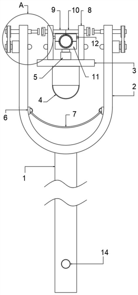
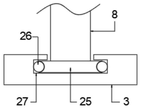
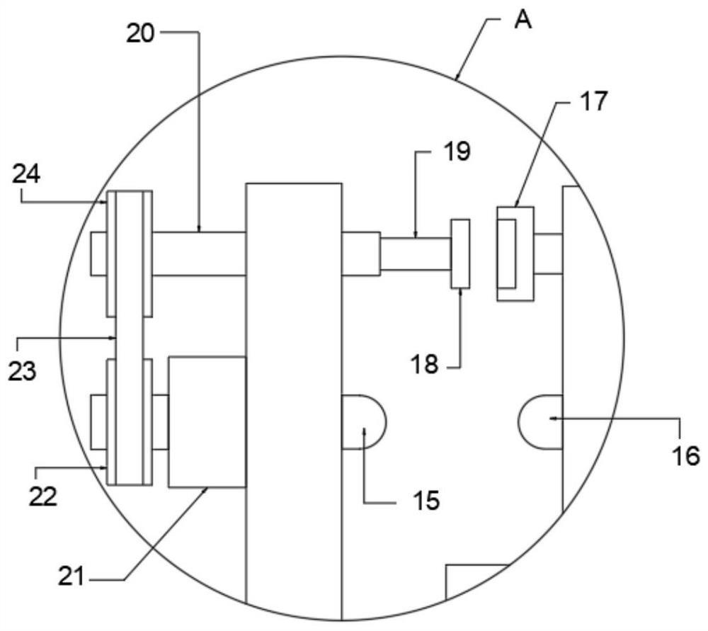
The invention discloses a line fault indicator dismounting structure for power equipment. The dismounting structure comprises an insulating rod and a fault indicator mounting plate, the insulating rodis fixedly connected with a U-shaped rod, the U-shaped rod is symmetrically and rotatably connected with sleeve shafts, one side of the U-shaped rod is fixedly provided with micro motors, and the output ends of the micro motors are fixedly connected with output shafts; and transmission mechanisms are arranged between the output shafts and the sleeve shafts, a rectangular telescopic rod is slidably inserted into each sleeve shaft in a penetrating mode, and a magnetic clamping block is fixedly connected to the end, away from the corresponding sleeve shaft, of each rectangular telescopic rod. First chain wheels are driven by the micro motors to rotate quickly, so that the rectangular telescopic rods drive the magnetic clamping blocks to rotate quickly, sliding rods and a first limiting rod are driven to rotate oppositely under the clamping of the magnetic clamping blocks and magnetic heads, a threaded head begins to be separated from a threaded groove until the threaded head is completely separated from the threaded groove, and quick disassembly work is completed; adn time and labor are saved.

Description

technical field [0001] The invention relates to the technical field of line fault indicators, in particular to a dismantling structure and a dismantling method of a line fault indicator for electric equipment. Background technique [0002] Fault indicator refers to a device installed on power lines (overhead lines, cables and busbars) to indicate fault current. Most fault indicators can only identify and indicate short-circuit faults by detecting the characteristics of short-circuit current. Electromagnetic induction equipment that reflects a short-circuit current passing through and a fault sign (red card) appears. Install this fault indicator along the distribution line. Once the line fails and the short-circuit current flows, the fault indicator will act, and the red card of the fault sign will appear. Then patrol along the line, the fault indicators from the power supply side to the fault point all show red cards, and the fault indicators after the fault point do not sh...

Claims


Application Information

Patent Timeline
Patent Type & Authority Applications(China)
IPC IPC(8): H02G1/02
CPCH02G1/02
Inventor 刘正花
Owner SHANGHAI MUNICIPAL ELECTRIC POWER CO
Learn More