
Drill bit sleeve

A kind of drill sleeve and drill bit technology, which is applied in drilling/drilling equipment, parts of boring machine/drilling machine, measurement of positioning in boring machine/drilling machine, etc. It can solve the problems of large dust, difficult cleaning, drilling through plates, etc., and achieve Anti-splash operator, convenient control, and operator protection effect

Pending Publication Date: 2018-06-12
重庆聚陆新能源有限公司
View PDF0 Cites 2 Cited by
  • Summary
  • Abstract
  • Description
  • Claims
  • Application Information

AI Technical Summary

Problems solved by technology

Problems in the drilling process: 1. There is no sleeve on the outside of the traditional drill bit, and the high-speed flying drill bit will raise the dust, and the dust pollution is quite serious, especially when the wall and furniture are drilled during the post-construction of the interior that has been occupied. The operating dust is very large and difficult to clean; operators who inhale dust for a long time are also prone to pneumoconiosis, and various small particles are splashed around, which can easily hurt the operator's face and even eyes, and there are even emergencies, such as when the drill bit is rotating at a high speed Sudden breakage and flying out will cause unimaginable serious consequences; 2. Traditional drills cannot limit the drilling depth, so there are often situations where the drilling depth is not enough or the plate is drilled through

Method used


Image

  • Drill bit sleeve
  • Drill bit sleeve
  • Drill bit sleeve

Examples


Embodiment 1

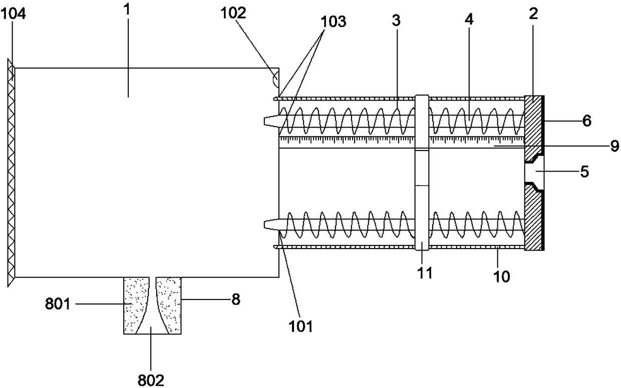
[0037] Such as figure 1 and 7 , a drill sleeve, including a cylinder 1, a base 2, and a guide member with an elastic member sheathed on the outside; the elastic member is a spring 3; the guide member is a plurality of stems circumferentially arranged on the base 4. One end of the stem is fixed on one side of the base 2, and the other end is movably arranged in the first through hole 101 opened on one side of the cylinder 1; the two ends of the spring 3 are respectively connected to the surface of the cylinder 1 and the base 2 The center of the base 2 is provided with a connection hole 5 for inserting the drill bit 100 and matching the surface of the drill tool 200 at the end of the drill bit; the base 2 and connection hole 5 are attached to the surface of the drill tool 200 at the end of the drill bit The joint is provided with a fastening structure; the fastening structure is a strong adhesive layer 6; the outer surface of the strong adhesive layer 6 is provided with a hand-...

Embodiment 2

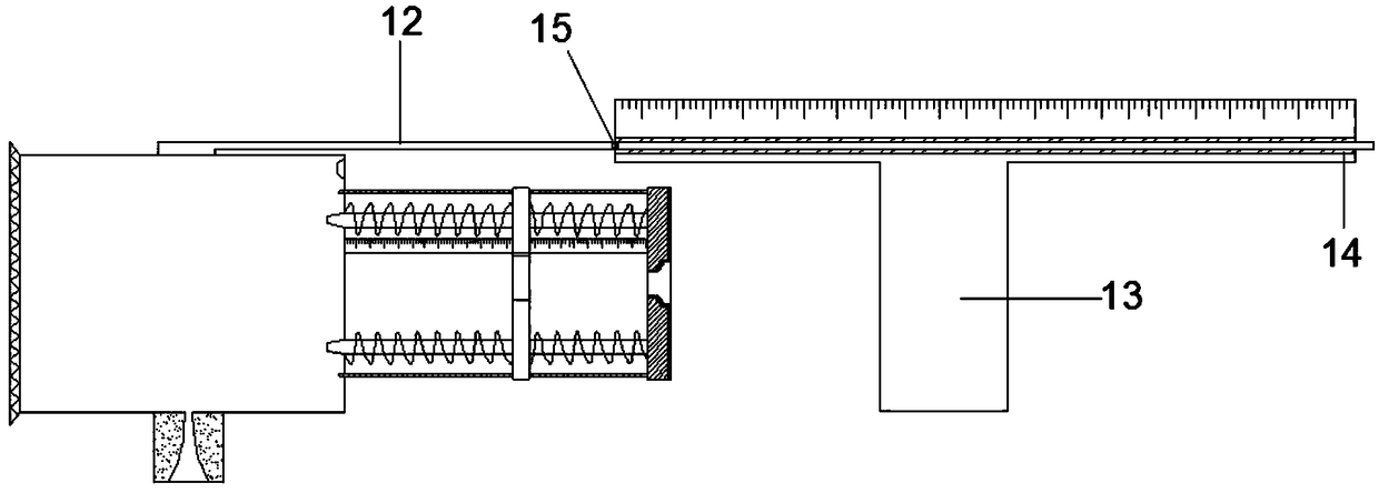
[0049] Such as figure 2 , The difference from Embodiment 1 is that this embodiment also includes a distance measuring rod 12 connected to the top of the cylinder 1, and a T-shaped ruler 13 that can be clamped on the drill tool 200; the T-shaped ruler 13 is equipped with There is a transparent observation hole 14 for the distance measuring rod 12 to slide through; a scale is marked above the transparent observation hole 14; the distance measuring rod has a zero mark 15 at the initial position corresponding to the scale in the initial state position. When in use, the distance / depth of the drilled hole by the electric drill is the distance that the cylinder 1 moves, and then reflected on the distance measuring rod 12 connected to it, the distance measuring rod 12 slides in the transparent observation hole 14, and the zero mark 15 points to the corresponding scale. This design enables the operator to know the distance / depth of the drilling in real time, facilitates the control of...

Embodiment 3

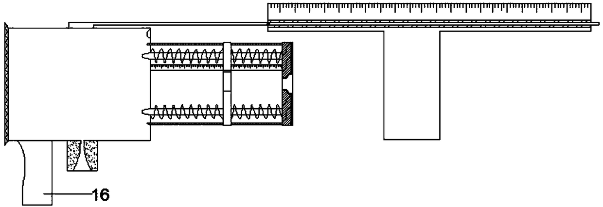
[0051] Such as image 3 , the difference from the second embodiment is that this embodiment also includes an auxiliary handle 16 connected to and arranged under the barrel 1 . When the operator uses the device, he holds the electric drill in one hand and the auxiliary handle 16 in the other hand, which can make the swing range of the cylinder body 1 smaller, and the stability and convenience of the equipment are better.


PUM


Abstract

The invention discloses a drill bit sleeve applied to the field of building construction equipment. The drill bit sleeve comprises a cylinder, a base and a guide piece sleeved with an elastic piece. Aconnecting hole allowing a drill bit to be inserted therein and matched with a drill bit tool profile at the tail end of the drill bit is formed in the center of the base. A fastening structure is arranged at the position where the base and the connecting hole are attached to the drill bit tool profile at the tail end of the drill bit. A dust collection connector connected with an external dust collector is arranged on the wall of the cylinder. A stroke control mechanism is further arranged between the cylinder and the base. Due to the fact that no sleeve is arranged outside a traditional drill bit, the drill bit can be severely polluted by dust, and evenly splashing injuries can be caused. The drilling depth of the traditional drill bit cannot be limited, and consequentially, the situation that the drilling depth is insufficient or a board is excessively drilled occurs frequently. The drill bit sleeve can be arranged outside a drill bit in a sleeving mode when a tool such as an electric hand drill / impact drill is in use, so that dust and splashing are prevented, an operator is protected, and the drilling depth can be limited.

Description

technical field [0001] The invention belongs to the field of building construction equipment, and in particular relates to a drill bit sleeve, which is suitable for being set on the outside of drill bits such as electric hand drills, impact drills, and bench drills. Background technique [0002] During construction, especially when home furnishing, such as wall lamps, wall cabinets, water heaters, televisions and other electrical appliances that need to be hung on the wall, it is necessary to use a hand drill / impact drill to clean walls, stones and wood. Make holes. Problems in the drilling process: 1. There is no sleeve on the outside of the traditional drill bit, and the high-speed flying drill bit will raise the dust, and the dust pollution is quite serious, especially when the wall and furniture are drilled during the post-decoration construction of the house that has been occupied. The operating dust is very large and difficult to clean; operators who inhale dust for a...

Claims


Application Information

Patent Timeline
Patent Type & Authority Applications(China)
IPC IPC(8): B23B49/02B23Q11/08B23Q17/22B23Q17/00
CPCB23B49/02B23Q11/08B23Q17/00B23Q17/22
Inventor 陆帅
Owner 重庆聚陆新能源有限公司
Learn More