Power generation structure and door magnetic switch

A door magnetic switch and soft magnetic technology, applied in the field of switches, can solve problems such as inconvenience in use, and achieve the effects of high power generation efficiency, compact structure and simple magnetic circuit

Pending Publication Date: 2020-12-29
CHANGZHOU INST OF TECH
View PDF0 Cites 0 Cited by
  • Summary
  • Abstract
  • Description
  • Claims
  • Application Information

AI Technical Summary

Problems solved by technology

[0007] In order to solve the technical problem of inconvenient use of battery-type wireless switches in the prior art, the present invention proposes a power generation structure, which can generate electricity by itself, without installing batteries, and is easy to use

Method used


Image

  • Power generation structure and door magnetic switch
  • Power generation structure and door magnetic switch
  • Power generation structure and door magnetic switch

Examples


Embodiment 1

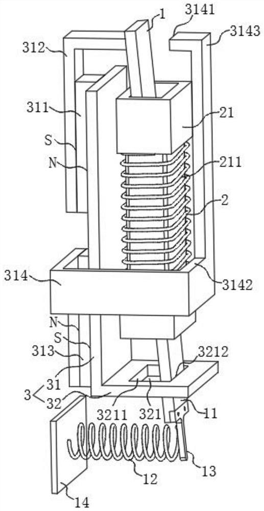
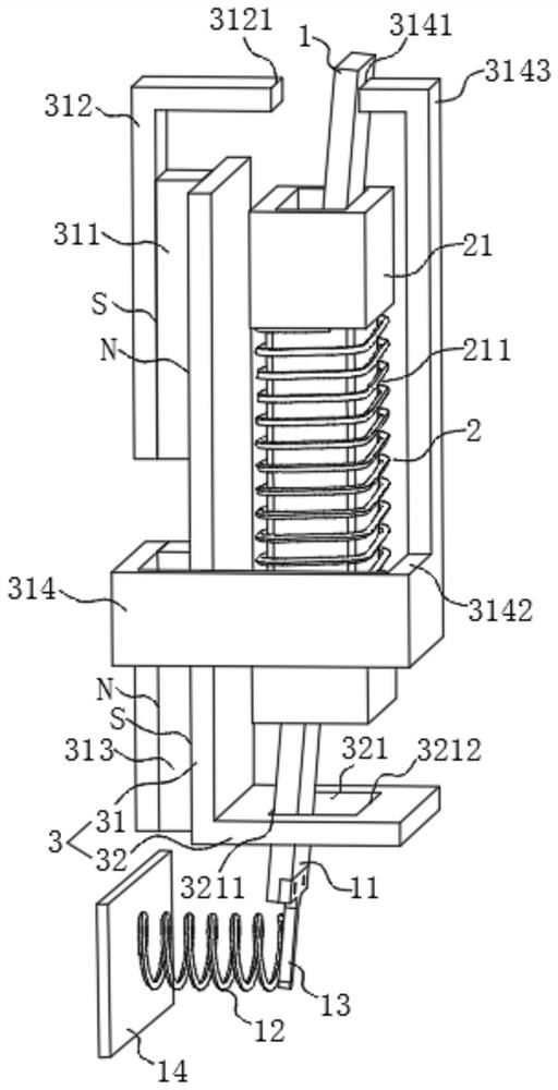
[0057] Such as Figure 1-2 As shown, the power generation structure of this embodiment includes a soft magnetic plate 1 and a coil 2 arranged around the soft magnetic plate 1 , wherein the soft magnetic plate 1 is configured to be rotatably installed, and the coil 2 is configured to be fixedly installed. The power generation structure of this embodiment also includes a soft magnetic frame 3, the soft magnetic frame 3 includes a fixed portion 31 and a bending portion 32 bent from the fixed portion 31 to the soft magnetic plate 1, and the fixed portion 31 is fixedly arranged on the soft magnetic plate 1 and one side of the coil 2, and the first end of the fixed part 31 is provided with a first permanent magnet 311, and the second end of the fixed part 31 is provided with a second permanent magnet 313, and the first permanent magnet 311 and the second permanent magnet 313 can be It is magnetically adsorbed to the fixed part 31, and can also be fixed to the fixed part 31 by screwi...

Embodiment 2

[0072] Such as Figure 5-7 As shown, the door magnetic switch of this embodiment includes a housing 4 built in a carrier, the carrier may be a refrigerator or a door frame, etc., the housing 4 is integrated with the power generation structure and the driving board 41 of the first embodiment, and the driving board 41 is Configured as a rotational installation, the drive plate 41 is used to drive the soft magnetic plate 1 to deflect, specifically, as Figure 8 As shown, the coil support 21 in the power generation structure is fixedly connected to the housing 4 through the fixed rod 22, the soft magnetic frame 3 is also directly fixedly connected to the housing 4, and the driving board 41 is an L-shaped driving board. In the initial state, the L-shaped driving The first section of the plate is parallel to the first surface of the fixed part 31 of the soft magnetic frame 3, and the middle part of the first section of the L-shaped driving plate is hinged with a rotating shaft 44, s...

Embodiment 3

[0080] Such as Figure 11 As shown, the difference between the magnetic door switch of the present embodiment and the second embodiment is that the magnetic assembly of the present embodiment includes at least one fourth permanent magnet 43 instead of the third permanent magnet 42 in the second embodiment, and the fourth permanent magnet The magnet 43 is configured at the second end of the first section of the driving plate 41, and the fourth permanent magnet 43 and the door panel 5 attract each other, specifically, as Figure 11 As shown, the left end of the fourth permanent magnet 43 is an N pole, the right end is an S pole, and the left end of the door panel 5 is an N pole or the door panel 5 as a whole is a non-magnetic iron-containing metal plate, so that the right end of the fourth permanent magnet 43 It is different from the magnetism at the left end of the door panel 5, because opposites attract each other, the third permanent magnet 42 and the door panel 5 attract eac...


PUM


Abstract

The invention relates to the technical field of switches, in particular to a power generation structure which comprises a soft magnetic plate, a coil and a soft magnetic frame, the soft magnetic plateis configured to be rotatably installed, the coil is arranged around the soft magnetic plate, the soft magnetic frame comprises a fixing part and a bending part, and a first permanent magnet is arranged at the first end of the fixing part. A second permanent magnet is arranged at the second end of the fixing part, a receding opening allowing the soft magnetic plate to rotate is formed in the bending part, a first concentrating flux plate is connected to the first permanent magnet, the first concentrating flux plate is bent to form a first contact part, the first contact part is located on oneside of the soft magnetic plate, the second permanent magnet is connected with a second concentrating flux plate, the second concentrating flux plate is bent to form a second contact part, and the second contact part is located on the other side of the soft magnetic plate. The power generation structure provided by the invention is convenient to use, compact in structure, convenient to integrateinto a module, high in power generation efficiency and large in induction current.

Description

technical field [0001] The invention relates to the technical field of switches, in particular to a power generation structure and a door magnetic switch. Background technique [0002] With the continuous development of electronic technology, wireless technology is playing an increasingly important role in intelligence. At present, there are wireless switches that use wireless technology to control household appliances. The existing wireless switches can be divided into battery-type wireless switches and Self-generating wireless switches, the use of these wireless switches greatly facilitates people's daily life. [0003] However, the existing wireless switches have the following problems: [0004] 1. The battery-type wireless switch needs to be installed with a rechargeable battery. Since the switch is in a wireless connection state, the battery needs to be taken out and charged frequently. Because the user often forgets to charge, it is misjudged as a power failure when u...

Claims


Application Information

Patent Timeline
IPC IPC(8): H02K35/02H02K7/18H02K1/12H02K1/34
CPCH02K1/12H02K1/34H02K7/1876H02K35/02
Inventor 李春光
Owner CHANGZHOU INST OF TECH
Why Eureka
Try Eureka