driving aids
A technology of auxiliary devices and safety devices, which is applied in the directions of control devices, pedestrian/occupant safety arrangement, transportation and packaging, etc., can solve the problems of insufficient reduction of collision risk and reduction of collision safety.
- Summary
- Abstract
- Description
- Claims
- Application Information
AI Technical Summary
Problems solved by technology
Method used
Image
Examples
no. 1 approach
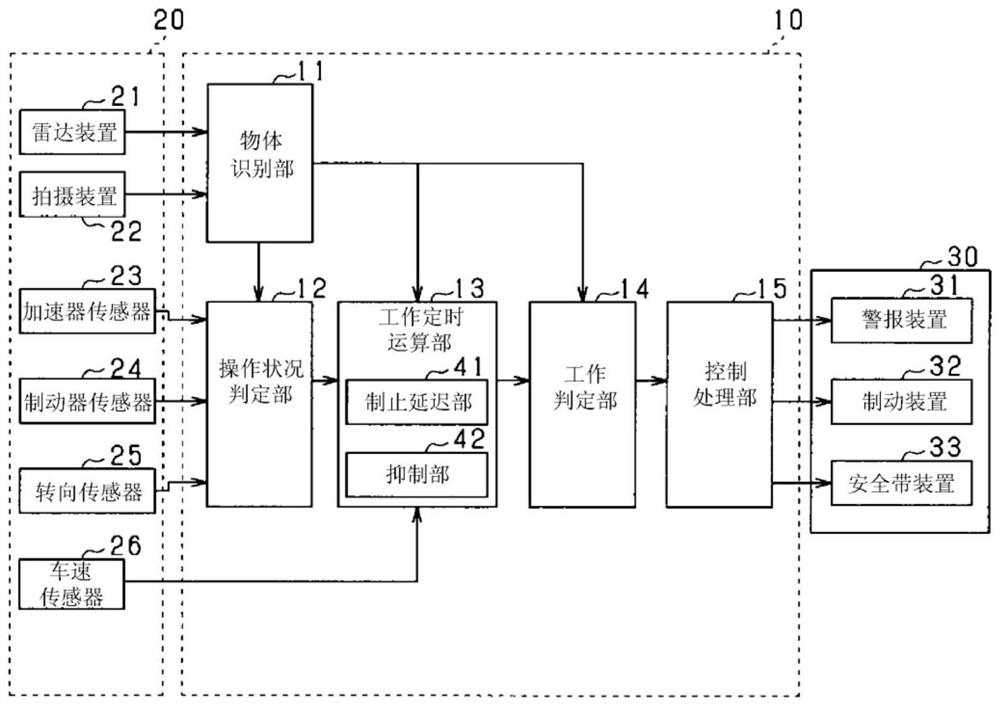
[0020] figure 1 The driving assistance system 1 according to the present embodiment is shown. The driving assistance system 1 includes an ECU 10 , sensors 20 , and a safety device 30 . The ECU 10 is mounted on the vehicle and is a driving assistance device that assists the driving of the vehicle. It has a function as a PCS system and performs control based on the detected information of an object existing around the vehicle to avoid collision with the object or reduce collision damage. . Detection information of the sensors 20 is input to the ECU 10 . The ECU 10 controls the safety device 30 based on the input detection information.
[0021] The sensors 20 include a radar device 21 , an imaging device 22 , an accelerator sensor 23 , a brake sensor 24 , a steering sensor 25 , and a vehicle speed sensor 26 . The radar device 21 and the imaging device 22 function as object detection devices that detect objects around the host vehicle.
[0022] The radar device 21 is, for exa...
no. 2 approach
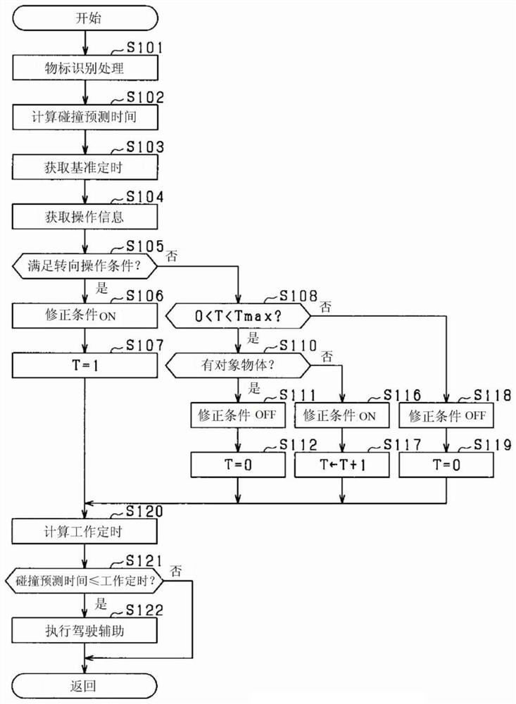
[0079] use Figure 6 The flow chart of FIG. 2 describes the processing procedure of the driving assistance control executed by the ECU 10 of the second embodiment. This process is performed for each object existing ahead in the traveling direction of the own vehicle every predetermined control cycle. exist Figure 6 In the processing shown, the correction condition is changed in accordance with whether the object detected on the route of the host vehicle after the steering operation is the same vehicle as that before the steering operation. image 3 The treatment shown is different. In addition, due to Figure 6 The processes shown in steps S301 to S307, and steps S320 to S322 in image 3 The respective processes shown in steps S101 to S107 and steps S120 to S122 are the same, and therefore descriptions are omitted by substituting the reference numbers in the S100 series for the S300 series.
[0080] In the present embodiment, when the operation information is not that th...
other Embodiment approach
[0097] In the first or second embodiment described above, the object recognition unit 11 may set a dangerous area in a predetermined area including at least the side of the host vehicle. For example, if Figure 9 As shown, the dangerous area 53 can be set as a predetermined area extending forward or rearward along the route 73 of the own vehicle 60 on the side of the own vehicle 60 .
[0098] In the case of hazardous area settings, the image 3 Between step S104 and step S105 shown, or, Figure 6 Shown between step S304 and step S305 Figure 10 treatment shown.
[0099] Such as Figure 10 As shown, first, in step S401, the dangerous area is set. Next, in step S402, it is determined whether a target object is detected in the dangerous area. In step S402, when the target object is detected in the dangerous area, the process proceeds to step S403, and the threshold value X for determining the presence or absence of a steering operation is changed. That is, the threshold va...
PUM
 Abstract
Description
Claims
Application Information
 - R&D
- Intellectual Property
- Life Sciences
- Materials
- Tech Scout
- Unparalleled Data Quality
- Higher Quality Content
- 60% Fewer Hallucinations
Browse by: Latest US Patents, China's latest patents, Technical Efficacy Thesaurus, Application Domain, Technology Topic, Popular Technical Reports.
© 2025 PatSnap. All rights reserved.Legal|Privacy policy|Modern Slavery Act Transparency Statement|Sitemap|About US| Contact US: help@patsnap.com


