Steel pipe cutting and punching machine

A technology of punching machine and steel pipe, which is applied in the field of steel pipe processing, can solve the problems that automatic punching and cutting cannot be realized, and achieve the effect of convenient maintenance

Active Publication Date: 2021-01-01
QINGDAO HUIJINTONG ELECTRIC POWER EQUIP
View PDF5 Cites 3 Cited by
  • Summary
  • Abstract
  • Description
  • Claims
  • Application Information

AI Technical Summary

Problems solved by technology

[0002] In the process of steel pipe processing, it is often necessary to cut and punch steel pipes. Usually, the steel pipes are operated by manually operating cutting machines and punching machines, but it is a test of workers'

Method used


Image

  • Steel pipe cutting and punching machine
  • Steel pipe cutting and punching machine
  • Steel pipe cutting and punching machine

Examples


Embodiment

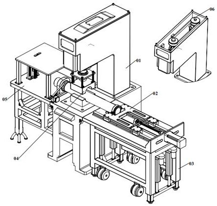
[0032] Example: such as figure 1 , figure 2 , image 3 , Figure 4 , Figure 5 , Figure 6 , Figure 7 , Figure 8 , Figure 9 , Figure 10 A steel pipe cutting and punching machine is shown. The shell system 1 is the base device, the shell system 1 is the installation platform of the mobile system 3 and the main system 5, the mobile system 3 is the installation platform of the propulsion system 2, the shell system 1 is the installation platform of the drive system 6, and the stamping system 4 is the drive system 6 installation platforms;

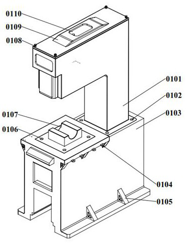
[0033] The concrete structure of shell system 1 is as follows figure 2 As shown, the lower shell 103 is placed on the ground, the rib plate 105 is fixedly installed on the lower shell 103, the lower shell 103 is provided with connecting ears 104, the connecting plate 106 is fixedly installed on the lower shell 103, and the lower clamping block 107 is fixedly installed on the connecting On the plate 106, the connecting plate 102...


PUM


Abstract

The invention discloses a steel pipe cutting and punching machine. The steel pipe cutting and punching machine comprises a shell system, a propelling system, a moving system, a punching system, a mainbody system and a driving system, the shell system is a base device, the shell system is a mounting platform of the moving system and the main body system, the moving system is a mounting platform ofthe propelling system, the shell system is a mounting platform of the driving system, the punching system is an mounting platform of the driving system, a steel pipe is placed on the shell system andthen fixed to the propelling system, the punching system punches the steel pipe, the head of the steel pipe is placed in the main body system, the main body system cuts the steel pipe, a steering motor on the main body system can control the steel pipe to rotate, a propelling motor of the propelling system can control translation of the steel pipe to achieve positioning of the steel pipe, and themoving system can be separated from the shell system to independently move so as to facilitate maintenance.

Description

technical field [0001] The invention relates to the technical field of steel pipe processing, in particular to a steel pipe cutting and punching machine. Background technique [0002] In the process of steel pipe processing, it is often necessary to cut and punch the steel pipe. Usually, the steel pipe is operated by manually operating the cutting machine and the punching machine, but it is a test of the worker's technology. In order to solve this problem, the application number: CN201620985896. 8 has announced a kind of steel pipe cutting punching machine, but this device can't realize automatic punching and cutting, and needs manual operation. Contents of the invention [0003] In view of the above technical problems, the present invention provides a steel pipe cutting and punching machine, including a shell system, a propulsion system, a moving system, a stamping system, a main body system, and a drive system; [0004] The shell system is a base device, the shell syste...

Claims


Application Information

Patent Timeline
IPC IPC(8): B23P23/04B21D28/04B21D28/28B23D45/12
CPCB23P23/04B23D45/12B21D28/28B21D28/04
Inventor 常永江
Owner QINGDAO HUIJINTONG ELECTRIC POWER EQUIP
Why Eureka
Try Eureka