Feeding equipment in assembly line

A technology for assembling lines and feeding equipment, which can be used in conveyors, conveyor objects, transportation and packaging, etc., and can solve problems such as the impact of parts precision and the impact and wear of conical parts.

Inactive Publication Date: 2021-01-01
广州赢帝工业设计有限公司
View PDF0 Cites 2 Cited by
  • Summary
  • Abstract
  • Description
  • Claims
  • Application Information

AI Technical Summary

Problems solved by technology

[0003] Because the transmission belt on the assembly line feeder is relatively flat, so that during the transmission of the tapered parts on the conveyor belt, if the factory power failure causes the assembly line feeder to stop running quickly, it is easy to make the tapered parts on the conveyor belt due to inertia. Roll forward to form an arc track, so that the conical parts will collide with each other and wear, which will affect the precision of the parts

Method used


Image

  • Feeding equipment in assembly line
  • Feeding equipment in assembly line
  • Feeding equipment in assembly line

Examples


Embodiment 1

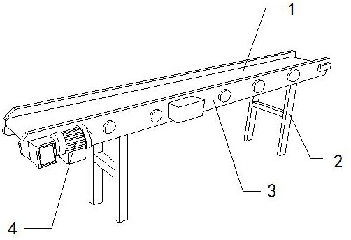
[0026]As for examplefigure 1 -exampleFigure 5 Shown:

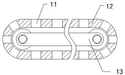
[0027]The present invention provides a feeding equipment in an assembly line. The structure includes a conveyor belt 1, a support frame 2, a bearing platform 3, and a driver 4. The support frame 2 is welded to the bearing platform 3, and the driver 4 is installed on the bearing platform 3. The conveyor belt 1 is movably engaged with the carrying platform 3; the conveyor belt 1 includes an introduction groove 11, a belt body 12, and a transmission frame 13. The introduction groove 11 and the belt body 12 are an integrated structure. The belt body 12 is movably engaged with the transmission frame 13.

[0028]Wherein, the introduction groove 11 includes an outer frame a1, an elastic ring a2, a shrink frame a3, and a lower shrink plate a4. The elastic ring a2 is installed between the bottom of the shrink frame a3 and the bottom of the inner wall of the outer frame a1. The frame a3 is movably engaged with the outer frame a1, the lower shri...

Embodiment 2

[0034]As for exampleFigure 6 -exampleFigure 8Shown:

[0035]Wherein, the outer frame a1 includes a force rod c1, a resilient bar c2, a frame c3, the force rod c1 is movably engaged with the frame c3, and the resilient bar c2 is installed between the force rod c1 and the frame c3 At the same time, the force rod c1 is provided with six, and three of them are a group of evenly distributed symmetrically on the inner side of the frame c3. The pressure rod c1 can be squeezed by the conical part to make the force rod c1 Shrink backward along the frame c3.

[0036]Wherein, the force rod c1 includes a contact plate c11, a suction plate c12, a reel c13, and a receiving plate c14. The contact plate c11 is movably engaged with the right side of the receiving plate c14 through the reel c13, and the suction plate c12 It is an integrated structure with the contact plate c11. The tapered part generates a leftward thrust to the contact plate c11, which can make the contact plate c11 shrink backwards to fi...


PUM


Abstract

The invention discloses feeding equipment in an assembly line. The feeding equipment structurally comprises a conveying belt, supporting frames, a bearing table and a driver. The supporting frames arewelded to the bearing table, the driver is installed on the right side of the bearing table, and the conveying belt is movably clamped to the bearing table. A conical part extrudes two clamping plates to enable the clamping plates to slide and being unfolded towards the two sides along a frame body; then boosting strips extrude the clamping plates to enable the two clamping plates to slide to themiddle part to clamp the conical part; and outer surface of the standing conical part extrudes a stress rod to enable the stress rod to be contracted inwards along the frame. Therefore, a springbackstrip can reversely push the outer surface of the stress rod to be attached to the outer surface of the standing conical part, so that an adsorption disc is adsorbed to the outer surface of the standing conical part, and the stress rod can fix the position of the standing conical part.

Description

Technical field[0001]The invention relates to the field of assembly lines, in particular to a feeding device in an assembly line.Background technique[0002]The feeder for the assembly line is mainly used for conveying the parts for assembly. By placing the parts for assembly on the conveyor belt of the feeder for the assembly line, the parts can be evenly conveyed to the next process through the conveyor belt. Common equipment of assembly line. Based on the above description, the inventor found that the feeding equipment in an existing assembly line mainly has the following shortcomings, for example:[0003]Because the transmission belt on the feeder for the assembly line is relatively flat, so that when the tapered parts are conveyed on the conveyor belt, the power outage of the factory causes the feeder for the assembly line to quickly stop running, and the tapered parts on the conveyor belt are easily caused by inertia. Rolling forward to form an arc-shaped trajectory, so that the t...

Claims


Application Information

Patent Timeline
Patent Type & Authority Applications(China)
IPC IPC(8): B65G15/58B65G15/30B65G41/00B65G47/18
CPCB65G15/30B65G15/58B65G41/00B65G47/18
Inventor 孙娜
Owner 广州赢帝工业设计有限公司
Why Eureka
Try Eureka