Embedded beam falling prevention device

An anti-falling beam, built-in technology, applied in the direction of bridges, bridge parts, bridge construction, etc., can solve problems such as beam damage

Active Publication Date: 2021-01-01
INST OF ENG MECHANICS CHINA EARTHQUAKE ADMINISTRATION
View PDF9 Cites 7 Cited by
  • Summary
  • Abstract
  • Description
  • Claims
  • Application Information

AI Technical Summary

Problems solved by technology

[0003] The present invention intends to provide a built-in anti-falling beam device to solve the problem that the anti-f...

Method used


Image

  • Embedded beam falling prevention device
  • Embedded beam falling prevention device
  • Embedded beam falling prevention device

Examples


Embodiment

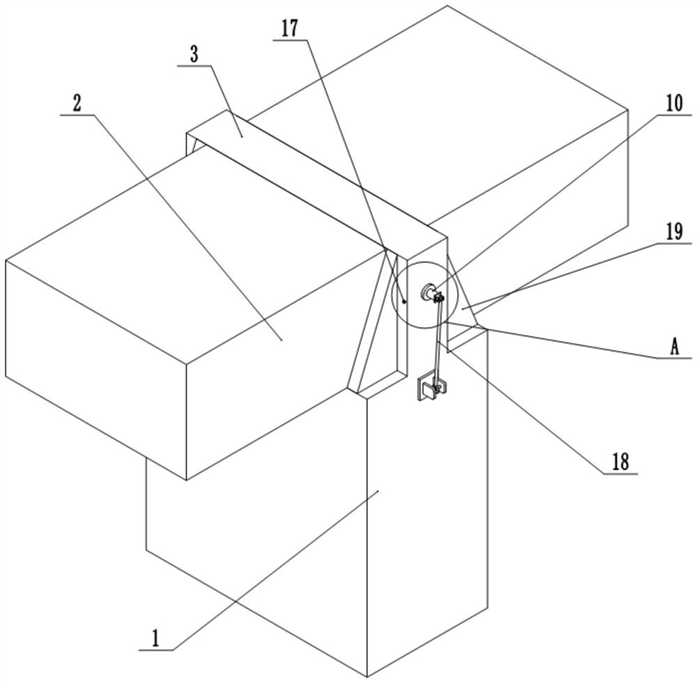
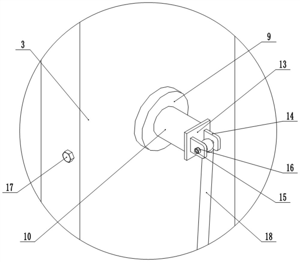
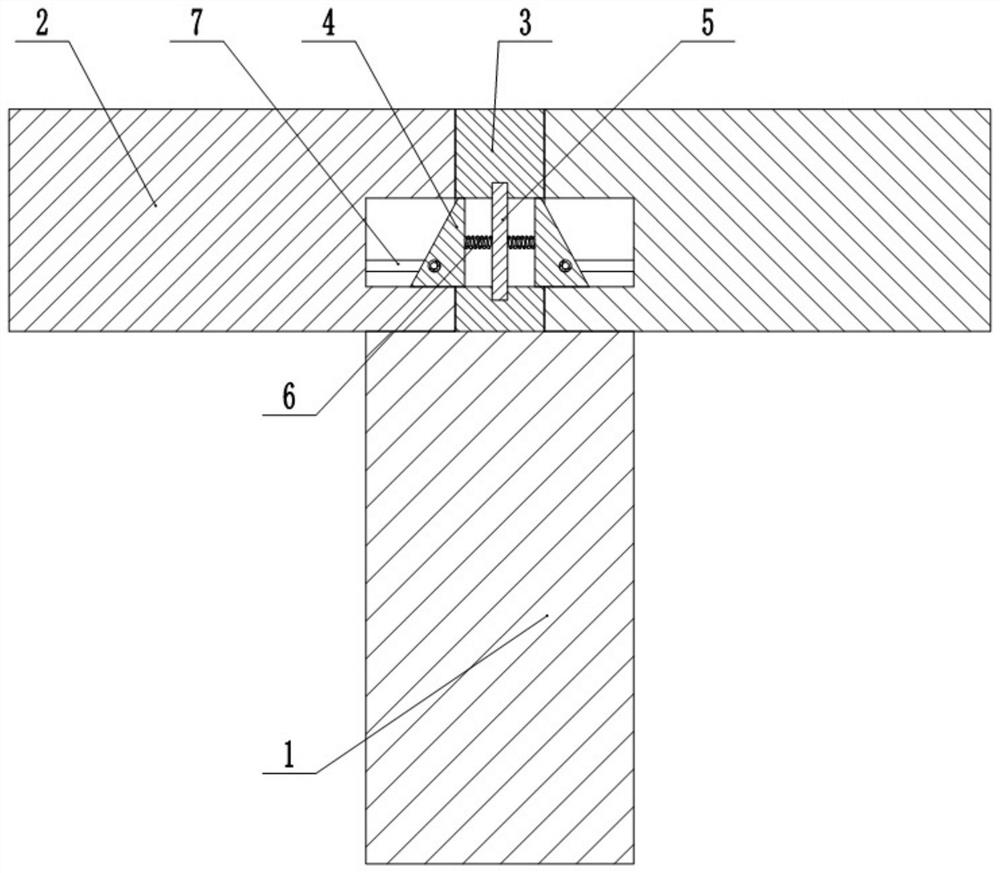
[0024] Such as figure 1 , figure 2 , image 3 , Figure 4 , Figure 5 and Figure 6 Shown: a built-in anti-drop beam device, including a bridge pier 1, the upper surface of the bridge pier 1 is fixed with a partition 3, the partition 3 is perpendicular to the bridge pier 1, and the partition 3 is provided with a horizontally arranged through groove, inside the through groove The limit column 4 is horizontally slidably connected, and the two ends of the limit column 4 protrude from the through groove, and the end faces at both ends of the limit column 4 are all inclined inwardly. Positioning column 5 is arranged to the direction, and the diameter of positioning column 5 contacts with the side wall of chute, and the two ends of positioning column 5 pass through limit column 4 and connect with the inner wall of through groove, and the two ends of chute are all fixed with toward positioning bar. Spring 6; two sections of beam body 2 are placed on the pier 1, the beam body 2 ...

specific Embodiment approach

[0025] Lift the beam body 2 at the left end and place it at the specified position. During the process of lowering the beam body 2 at the left end, the beam body 2 squeezes the inclined surface at the left end of the limit column 4, so that the limit column 4 slides to the right, and the beam body 2 at the left end reaches the designated position. After the position, the limit column 4 slides to the initial position under the action of the spring 6 and the positioning column 5, and the left end of the limit column 4 stretches into the cavity of the left end beam body 2; The limit rod 8 on the side is squeezed by the inner wall of the cavity and slides into the groove until the limit rod 8 contacts the limit groove 7. At this time, the limit rod 8 pops up under the action of the spring 6 and extends into the limit In groove 7; Place the beam body 2 at the right end after hoisting and place it at the designated position. During the process of putting down the beam body 2 at the r...


PUM


Abstract

The invention relates to the field of bridge construction, and particularly discloses an embedded beam falling prevention device which comprises a pier, a partition plate is fixed to the upper surfaceof the pier, the partition plate is perpendicular to the pier, a horizontally-arranged through groove is formed in the partition plate, a limiting column is horizontally and slidably connected into the through groove, the two ends of the limiting column extend out of the through groove, the end faces of two ends of limiting column are both inclined inwards; a sliding groove is vertically formed in the limiting column, a positioning column is vertically arranged in the sliding groove, the diameter of the positioning column makes contact with the side wall of the sliding groove, the two ends ofthe positioning column penetrate out of the limiting column to be connected with the inner wall of the through groove, and springs facing the positioning rod are fixed to the two ends of the slidinggroove; two sections of beam bodies are placed on the pier, the beam bodies are symmetrically placed relative to the partition plate, the upper surfaces of the beam bodies are flush with the upper surface of the partition plate, cavities are formed in the ends of the beam bodies, and the inner diameters of the cavities are equal to the outer diameter of the limiting column. The invention aims to solve the problem that the anti-falling beam facility and the beam bodies are rigidly impacted and the beam bodies are easily damaged during an earthquake.

Description

technical field [0001] The invention relates to the technical field of bridge construction, and specifically discloses a built-in anti-drop beam device. Background technique [0002] my country is one of the countries with the strongest seismic activity and the most severe earthquake disasters in the world, especially in the three seismically active regions of North China, Northwest China, and Southwest China, where there have been instances of falling beams caused by earthquakes. Beam falling is one of the bridge earthquake disasters with the highest frequency, the most destructiveness and the most difficult repair. The damage forms of the earthquake to the bridge superstructure include falling beam damage, collision damage, and support deviating from its guide groove or bottom basin, resulting in loss of horizontal bearing capacity. The main structural measures of the traditional anti-fall beam method are to set concrete blocks, anchor bolts or steel brackets on both side...

Claims


Application Information

Patent Timeline
IPC IPC(8): E01D19/00
CPCE01D19/00
Inventor 孙得璋何先龙戴君武张昊宇李思汉
Owner INST OF ENG MECHANICS CHINA EARTHQUAKE ADMINISTRATION
Why Eureka
Try Eureka