Rotor, motor and compressor

A technology of rotor and rotor core, which is applied in the field of compressors and rotors, and can solve problems such as reducing the working efficiency of motors

Pending Publication Date: 2021-01-01
ANHUI MEIZHI PRECISION MFG
View PDF0 Cites 0 Cited by
  • Summary
  • Abstract
  • Description
  • Claims
  • Application Information

AI Technical Summary

Problems solved by technology

[0002] The harmonic magnetic field generated when the motor is working makes the motor generate noise and reduces the working efficiency of the motor, so how to adjust the harmonic magnetic field to reduce noise and improve the working efficiency of the motor has become an urgent problem to be solved

Method used


Image

  • Rotor, motor and compressor
  • Rotor, motor and compressor
  • Rotor, motor and compressor

Examples


Embodiment 1

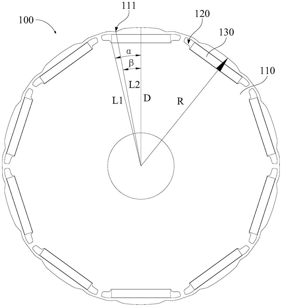
[0043] combine figure 1 , figure 2 and image 3 As shown, the embodiment of the first aspect of the present invention provides a rotor 100 including: a rotor core 110 , a magnet slot 120 and a permanent magnet 130 . The outer edge of the rotor core 110 is provided with grooves 111, and there are multiple magnet slots 120, and the plurality of magnet slots 120 are arranged on the rotor core 110 along the circumferential direction of the rotor core 110; the permanent magnets 130 are arranged in the magnet slots 120 and form magnetic poles , set the center line of any magnetic pole passing through the axis of the rotor core 110 as the D axis; set the circle passing through the outermost contour of the radial section of the rotor core 110 as the contour circle, and the center of the contour circle passes through the rotor core 110; the section of the permanent magnet 130 along the radial direction of the rotor core 110 is set as the section M, the line connecting the center of ...

Embodiment 2

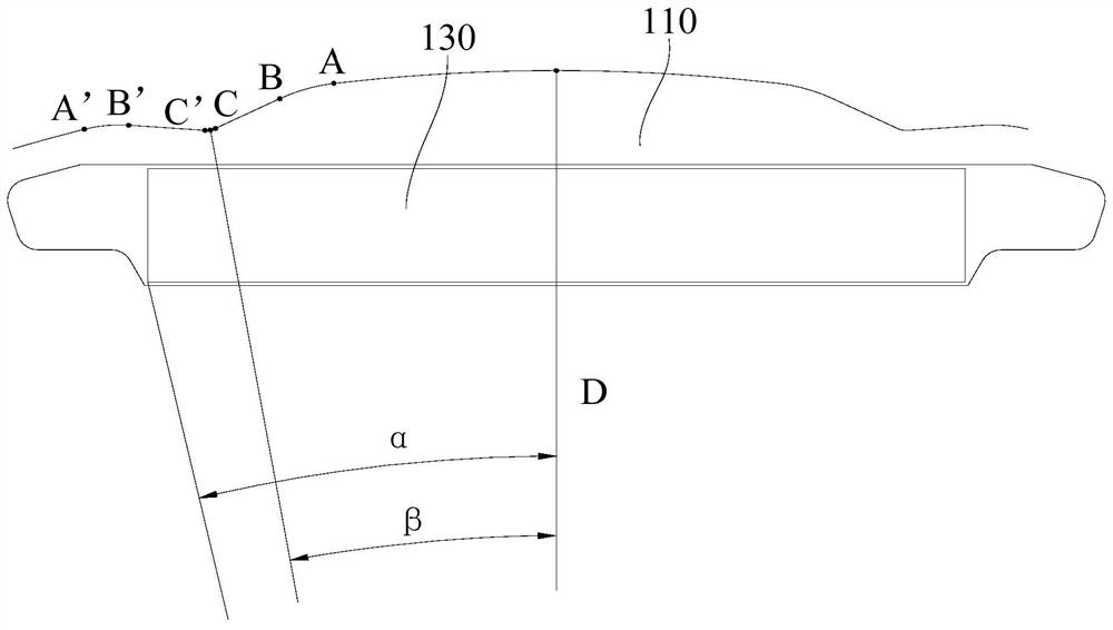
[0055] combine figure 1 , figure 2 , image 3 and Figure 4 As shown, on the basis of Embodiment 1, along the radial direction of the rotor core 110, the cross section of the groove 111 includes: a first arc segment AB and a second arc segment A'B', the first arc segment AB and the second arc segment A'B' are located on both sides of the connecting line L2.

[0056] In this embodiment, the first arc segment AB and the second arc segment A'B' are located on both sides of the connecting line L2, specifically, the groove 111 can be provided and the rotor core 110 can be provided with no groove 111. Part of the transition is through a circular arc segment, that is, there is a circular arc segment between the part of the rotor core 110 that is not provided with the groove 111 and the center line of the groove 111, and by setting the first circular arc segment AB and the second circular arc segment A'B' can avoid the sudden change of the radial dimension of the rotor core 110 a...

Embodiment 3

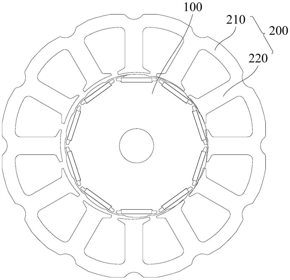
[0064] combine figure 1 , figure 2 , image 3 and Figure 4 As shown, the embodiment of the second aspect of the present invention proposes a motor, including: the rotor 100 in any of the above-mentioned embodiments, so the motor provided by the present invention has all of the rotor 100 provided in any of the above-mentioned embodiments benefit.

[0065] The stator 200 is provided with a mounting port, and the rotor 100 can be installed in the fish mounting port. The stator 200 and the rotor 100 are arranged concentrically, so that the stator 200 and the rotor 100 can be matched. The stator 200 includes a stator yoke 210 and a stator tooth 220. The stator yoke 210 It is ring-shaped, and there are multiple stator teeth 220, and the plurality of stator teeth 220 are arranged on the stator yoke 210 along the circumferential direction of the stator yoke 210, and two adjacent stator teeth 220 are arranged at intervals, so as to facilitate winding coil.

[0066] combine figu...


PUM


Abstract

The invention provides a rotor, a motor and a compressor. The rotor comprises a rotor core, a magnet groove and a permanent magnet. The outer edge of the rotor core is provided with a groove, the permanent magnet is arranged in the magnet groove and forms a magnetic pole, and the center line of any magnetic pole passing through the axis of the rotor core is set as a D axis. The cross section of the permanent magnet along the radial direction of the rotor core is set as a cross section M, a connecting line from the center of the contour circle to any point on the cross section M is set as a connecting line L1, and the included angle between the connecting line L1 and the D axis is smaller than alpha. along the radial cross section of the rotor core, the connecting line of the groove bottomof the groove and the circle center of the contour circle is set as a connecting line L2, the included angle between the connecting line L2 and the D axis is beta, and 0.8 < beta/alpha < 0.85 is satisfied. The ratio of beta to alpha limits the forming position of the groove, so that the forming position of the groove is associated with the size of the rotor, the ratio of beta to alpha is limited between 0.8 and 0.85, the noise in the motor process can be reduced, and the working efficiency of the motor is improved.

Description

technical field [0001] The invention belongs to the technical field of motors, and in particular relates to a rotor, a motor and a compressor. Background technique [0002] The harmonic magnetic field generated when the motor works makes the motor generate noise and reduces the working efficiency of the motor. Therefore, how to adjust the harmonic magnetic field to reduce noise and improve the working efficiency of the motor has become an urgent problem to be solved. Contents of the invention [0003] The present invention aims to solve one of the technical problems existing in the prior art or related art. [0004] In view of this, the first aspect of the present invention proposes a rotor, including: a rotor core, the outer edge of the rotor core is provided with grooves; magnet slots, a plurality of magnet slots, a plurality of magnet slots along the rotor core The circumferential direction of the rotor core is set on the rotor core; the permanent magnet is set in the ...

Claims


Application Information

Patent Timeline
Patent Type & Authority Applications(China)
IPC IPC(8): H02K1/27
CPCH02K1/276H02K2213/03
Inventor 王玉龙刘法民邱小华江波李宏涛
Owner ANHUI MEIZHI PRECISION MFG
Why Eureka
Try Eureka