Motors and Compressors
A rotor iron core and magnet slot technology, applied in electromechanical devices, electrical components, electric components, etc., can solve problems affecting motor efficiency, vibration and noise, etc., and achieve the effect of improving convenience, easy maintenance, and reducing processing procedures.
- Summary
- Abstract
- Description
- Claims
- Application Information
AI Technical Summary
Problems solved by technology
Method used
Image
Examples
Embodiment 1
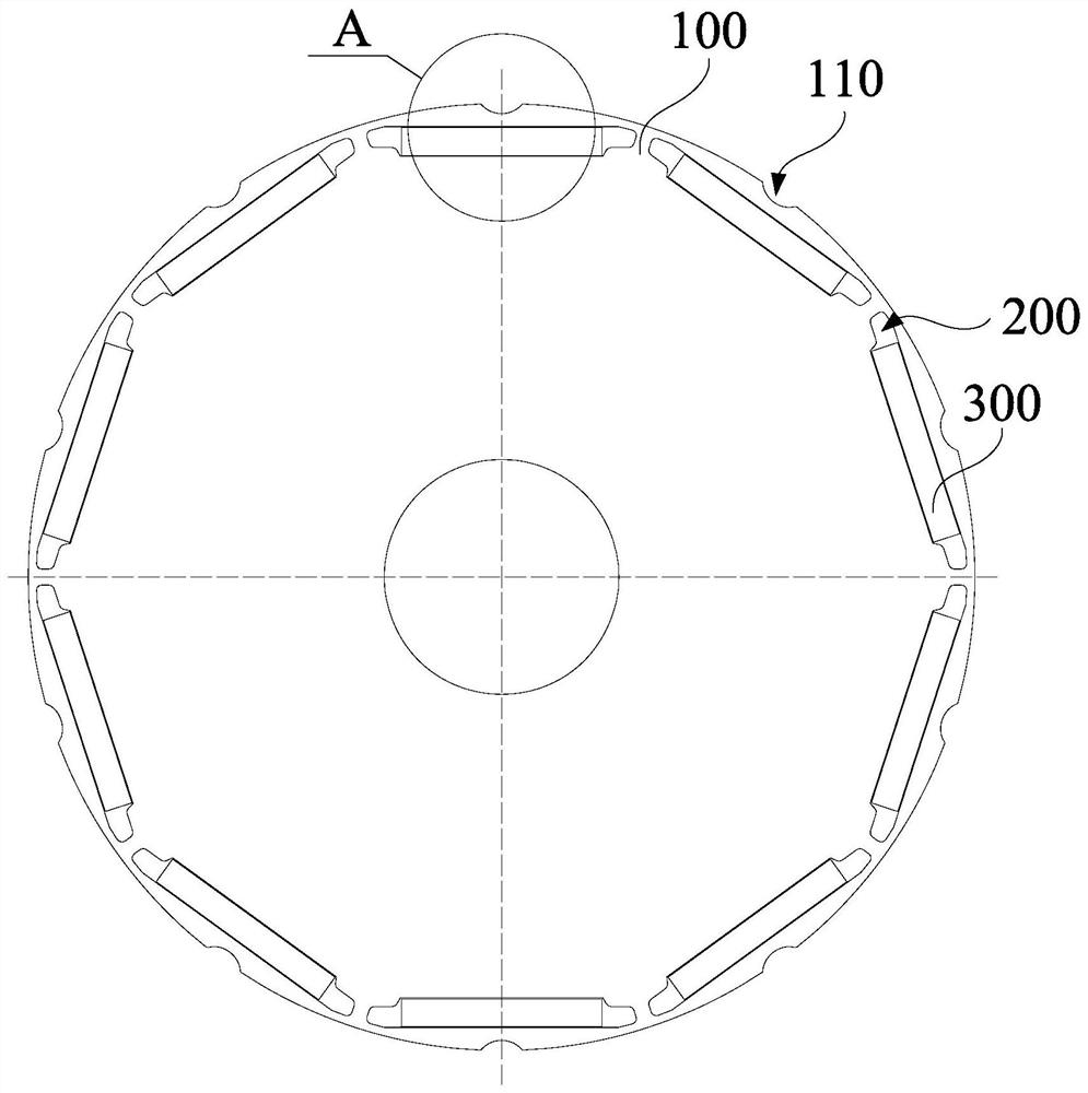
[0053] combine figure 1 and figure 2 As shown, the embodiment of the first aspect of the present invention proposes a motor, including: a rotor core 100 , a magnet slot 200 , and a permanent magnet 300 , and the magnet slot 200 is disposed on the rotor core 100 . There are a plurality of magnet slots 200, and the plurality of magnet slots 200 are arranged on the rotor core 100 along the circumferential direction of the rotor core 100; The center line of the magnetic pole is set as the D axis; the outer edge of the rotor core 100 is provided with a groove 110 , and the D axis passes through the groove 110 .
[0054] There are a plurality of magnet slots 200, and the plurality of magnet slots 200 are arranged on the rotor core 100 along the circumferential direction of the rotor core 100. The permanent magnets 300 can be installed in the magnet slots 200 and form magnetic poles, which can increase the magnetic flux. Function, since a plurality of magnet slots 200 are distribu...
Embodiment 2
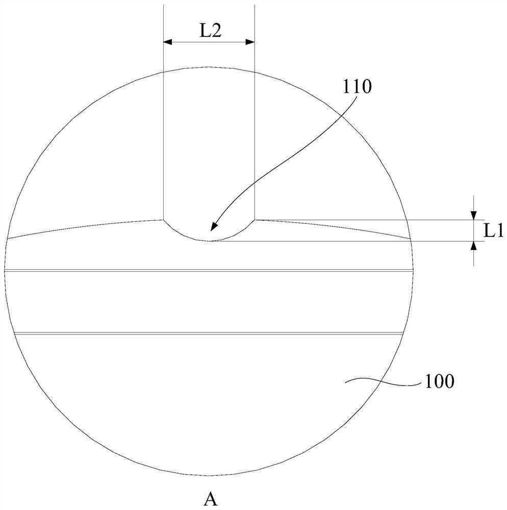
[0060] combine figure 1 , figure 2 , image 3 , Figure 4 and Figure 5 As shown, on the basis of Embodiment 1, an air gap is formed between the stator 400 and the rotor core 100; the maximum distance from the opening of the groove 110 to the bottom of the groove 110 is set as L1, and the minimum air gap is The value is δ, satisfying 0.3<L1 / δ<0.5.
[0061] In this embodiment, the maximum distance from the opening of the groove 110 to the bottom of the groove 110 is L1, and when the groove 110 is symmetrical with respect to the D axis, the maximum distance from the opening of the groove 110 to the bottom of the groove 110 The connecting line coincides with the center line of the groove 110. When the ratio of L1 to δ is greater than 0.5, it indicates that the depth of the groove 110 is relatively large. At this time, it is easy to affect the structural stability of the stator 400, and it is easy to over-adjust the third harmonic magnetic field. If the ratio of L1 to δ If ...
Embodiment 3
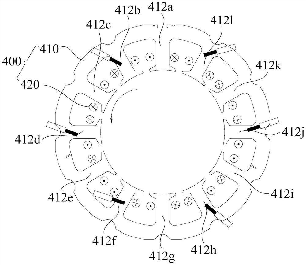
[0066] combine image 3 , Figure 4 and Figure 10 As shown, in the above embodiment, the stator 400 further includes: a stator core 410, including a stator yoke 411 and a stator tooth 412, the stator yoke 411 is configured in a ring shape, and the stator tooth 412 is connected to the stator yoke 411 and along the stator yoke 411 The circumferential interval of the yoke 411 is set in the stator yoke 411, and a winding slot 413 is formed between two adjacent stator teeth 412; the stator winding 420, the stator winding 420 includes a plurality of connected coils, and the coils are wound on On the plurality of stator teeth 412, the coils include first-type coils and second-type coils. Along the rotation direction of the rotor, the rotor passes through the second-type coils and the first-type coils in turn. The stator winding 420 is a three-phase stator winding 420. Each phase The stator winding 420 is provided with at least three joints, including a first joint, a second joint ...
PUM
 Abstract
Description
Claims
Application Information
 - R&D
- Intellectual Property
- Life Sciences
- Materials
- Tech Scout
- Unparalleled Data Quality
- Higher Quality Content
- 60% Fewer Hallucinations
Browse by: Latest US Patents, China's latest patents, Technical Efficacy Thesaurus, Application Domain, Technology Topic, Popular Technical Reports.
© 2025 PatSnap. All rights reserved.Legal|Privacy policy|Modern Slavery Act Transparency Statement|Sitemap|About US| Contact US: help@patsnap.com


