Rotor, motor, food processor, air supply device and household appliance

A technology for food processors and air supply devices, which is applied in the direction of electromechanical devices, motors, pump devices, etc., can solve problems such as the difficulty in realizing lightweight and miniaturized motors, increasing process complexity and production costs, and increasing rotor thickness, etc., to achieve Realization of weight reduction, miniaturization, and thickness reduction

Pending Publication Date: 2021-02-26
GUANGDONG MIDEA CONSUMER ELECTRICS MFG CO LTD
View PDF0 Cites 0 Cited by
  • Summary
  • Abstract
  • Description
  • Claims
  • Application Information

AI Technical Summary

Problems solved by technology

[0002] The motor is mainly composed of stator, rotor and end cover. The rotor is composed of magnets and multi-layer silicon steel sheets. There are two common ways to install magnets and multi-layer silicon steel sheets. One is to attach the magnets to the multi-layer silicon steel sheets. On the surface, this method increases the thickness of the rotor, and the magnet is easy to fall off from the multi-layer silicon steel sheet. The other is to embed the multi-layer magnet into the silicon steel sheet. In order to prevent the multi-layer silicon steel sheet from loosening, an additional rotor end ring is required. It is used to compress the silicon steel sheet. This method not only increases the complexity of the process and the production cost, but also increases the weight of the rotor, making it difficult to reduce the weight and miniaturization of the motor.

Method used


Image

  • Rotor, motor, food processor, air supply device and household appliance
  • Rotor, motor, food processor, air supply device and household appliance
  • Rotor, motor, food processor, air supply device and household appliance

Examples


Embodiment 1

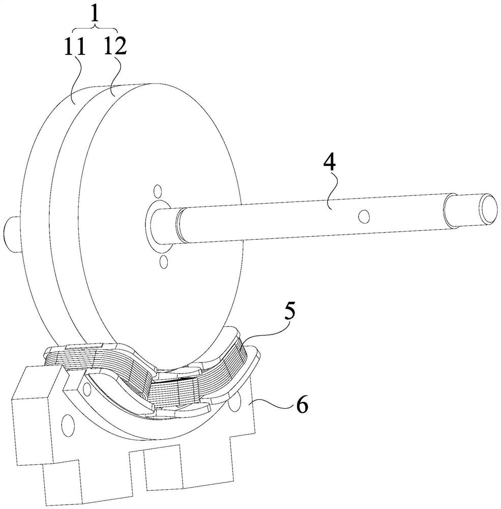
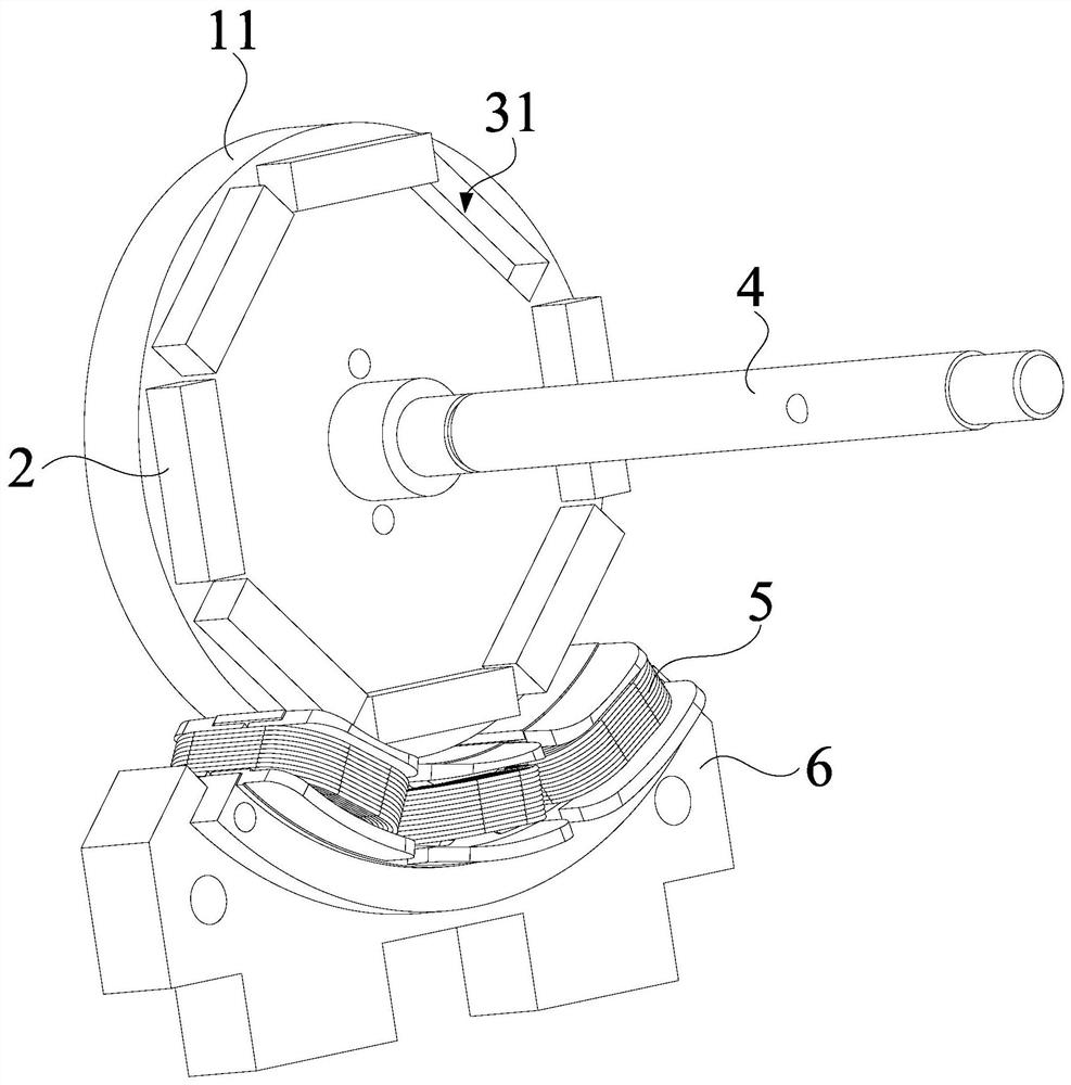
[0098] A rotor 9, combined with Figure 1 to Figure 6 As shown, it includes: a turntable 1 and a magnetic part 2. The turntable 1 includes a first bracket 11 and a second bracket 12. The first bracket 11 and the second bracket 12 form an accommodation space; 2 is set in the installation groove 3.

[0099] In this embodiment, the first bracket 11 and the second bracket 12 are used to replace the rotor core constructed of axially stacked silicon steel sheets in the related art, on the one hand, it is beneficial to reduce the weight of the rotor 9 and reduce the volume of the rotor 9, On the other hand, since the first bracket 11 and the second bracket 12 are not easy to loosen, the structural stability of the rotor 9 is ensured. Moreover, the thickness of the rotor 9 can also be reduced by accommodating the magnetic member 2 in the first bracket 11 and the second bracket 12 , thereby reducing the thickness of the motor, and realizing the weight reduction and miniaturization of ...

Embodiment 2

[0104] In any of the above embodiments, the installation groove 3 is provided on the first bracket 11 or the second bracket 12 .

[0105] In a specific embodiment, the first bracket 11 and the second bracket 12 are butted together. The installation slot 3 is disposed on the first bracket 11 , and the notch of the installation slot 3 faces the second bracket 12 .

[0106] In another specific embodiment, the first bracket 11 and the second bracket 12 are butted together. The installation slot 3 is disposed on the second bracket 11 , and the notch of the installation slot 3 faces the first bracket 11 .

[0107] In another specific embodiment, the first bracket 11 is arranged around the outer periphery of the second bracket 12 , and the installation groove 3 is provided on a side of the first bracket 11 facing the second bracket 12 .

[0108] In another specific embodiment, the first bracket 11 surrounds the outer periphery of the second bracket 12 , and the installation groove ...

Embodiment 3

[0110] The difference from the second embodiment is that the installation groove 3 is provided on the first bracket 11 and the second bracket 12 .

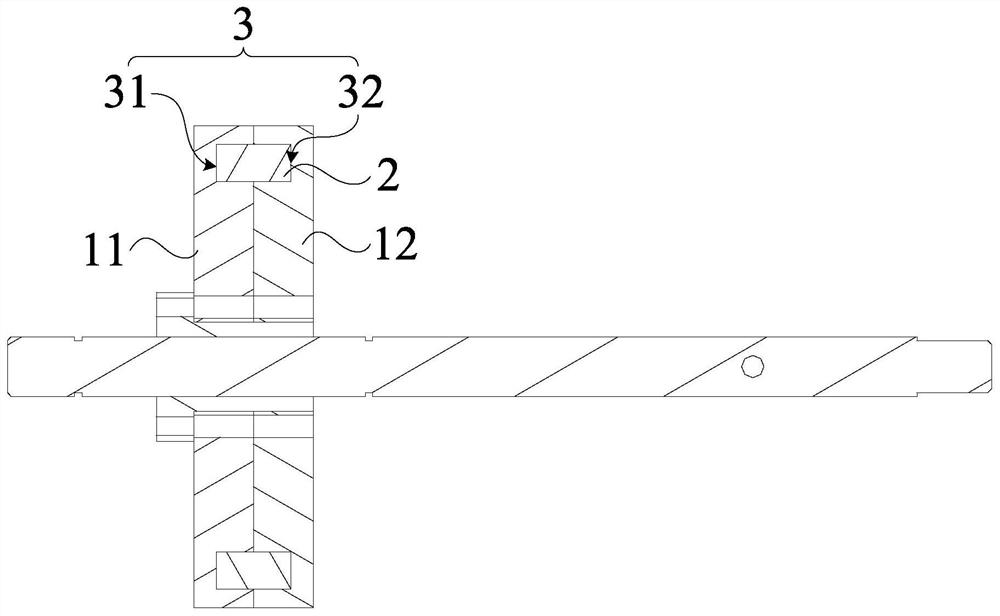
[0111] In a specific embodiment, combining Figure 2 to Figure 5 As shown, each installation groove 3 includes a first installation groove 31 and a second installation groove 32 . The first installation slot 31 is provided on the first bracket 11 , and the second installation slot 32 is provided on the second bracket 12 ;

[0112] In another specific embodiment, each installation groove 3 includes a first installation groove 31 and a second installation groove 32, the first installation groove 31 is arranged on the first bracket 11, and the second installation groove 32 is arranged on the second bracket 12 Above: the first installation slots 31 and the second installation slots 32 are alternately distributed, that is, each first installation slot 31 and each second installation slot 32 accommodates part of the magnetic component ...


PUM


Abstract

The invention provides a rotor, a motor with the rotor, a food processor with the motor, an air supply device and a household appliance. The rotor comprises a rotating disc and a magnetic piece; the rotating disc comprises a first support and a second support; the first support and the second support define a containing space, and the magnetic piece is arranged in the containing space. The first support and the second support are used for replacing multiple layers of silicon steel sheets, so the first support and the second support are not prone to loosening, the stability of the rotor structure is guaranteed, the first support and the second support are not prone to loosening, and a rotor end ring used for pressing the first support and the second support does not need to be independentlyarranged. Therefore, the weight of the motor is reduced, the thickness of the rotor can also be reduced by accommodating the magnetic pieces in the first bracket and the second bracket, the thicknessof the motor is further reduced, and the light weight and miniaturization of the motor are realized.

Description

technical field [0001] The invention belongs to the technical field of motor manufacturing, and specifically relates to a rotor, a motor, a food processor, an air supply device, a household appliance, an electric vehicle and a power generating device. Background technique [0002] The motor is mainly composed of stator, rotor and end cover. The rotor is composed of magnets and multi-layer silicon steel sheets. There are two common ways to install magnets and multi-layer silicon steel sheets. One is to attach the magnets to the multi-layer silicon steel sheets. On the surface, this method increases the thickness of the rotor, and the magnet is easy to fall off from the multi-layer silicon steel sheet. The other is to embed the multi-layer magnet into the silicon steel sheet. In order to prevent the multi-layer silicon steel sheet from loosening, an additional rotor end ring is required. It is used to compress the silicon steel sheet, which not only increases the complexity of...

Claims


Application Information

Patent Timeline
Patent Type & Authority Applications(China)
IPC IPC(8): H02K1/27H02K1/30H02K1/18H02K1/14H02K21/16H02K5/00A47J43/046A47J43/08F04D25/08
CPCA47J43/046A47J43/085F04D25/08H02K1/14H02K1/18H02K1/2706H02K1/30H02K5/00H02K21/16H02K2213/03Y02T10/64
Inventor 梁显堂陈炜杰王云峰陈连城刘锦泉
Owner GUANGDONG MIDEA CONSUMER ELECTRICS MFG CO LTD
Why Eureka
Try Eureka