Electric motors, compressors and refrigeration equipment
A compressor and magnetic isolation slot technology, applied in the direction of electromechanical devices, electrical components, electric components, etc., can solve the problems of frequent maintenance, affecting the normal use of the motor, demagnetization of permanent magnets, etc.
- Summary
- Abstract
- Description
- Claims
- Application Information
AI Technical Summary
Problems solved by technology
Method used
Image
Examples
Embodiment 1
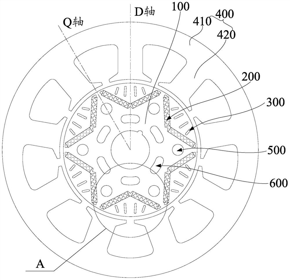
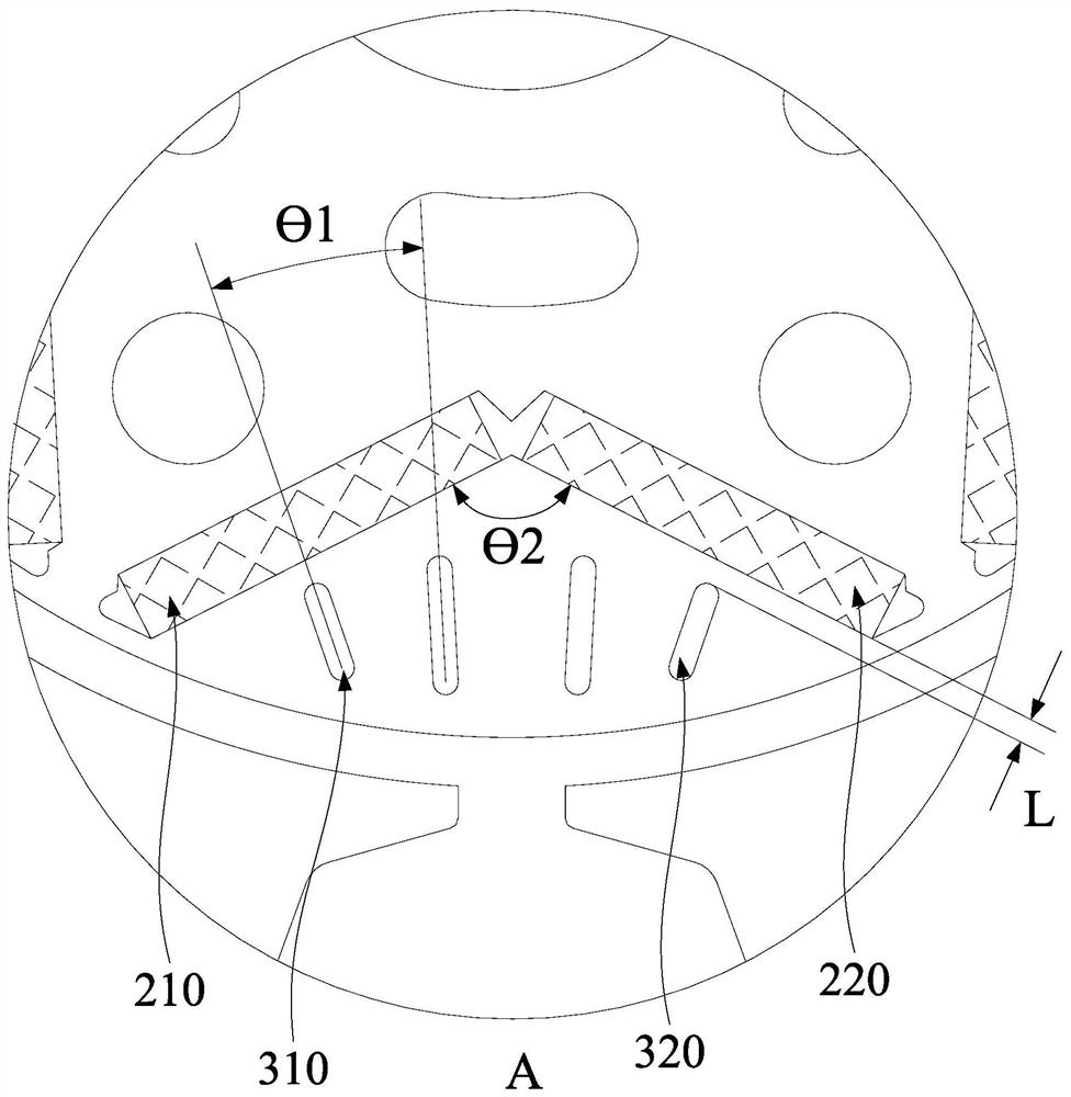
[0036] combine figure 1 and figure 2As shown, the embodiment of the first aspect of the present invention provides a motor, including: a rotor iron core 100, an installation slot 200 and a magnetic isolation slot 300, the installation slot 200 is arranged on the rotor iron core 100 along the circumferential direction of the rotor iron core 100; The magnetic isolation slot 300 is arranged on the rotor core 100 , and the magnetic isolation slot 300 is located between the installation slot 200 and the outer edge of the rotor core 100 .
[0037] The installation slot 200 can provide an installation position for the permanent magnet. By arranging the magnetic isolation slot 300 between the installation slot 200 and the outer edge of the rotor core 100, the magnetic isolation slot 300 can reduce the magnetization of the reverse magnetic field at the part where the rotor is easy to demagnetize, thereby The second permanent magnet is protected from being easily magnetized, the anti-...
Embodiment 2
[0045] combine figure 1 and figure 2 As shown, on the basis of the first embodiment, the installation groove 200 includes: a first groove body 210 and a second groove body 220, the first end of the second groove body 220 is connected to the first end of the first groove body 210, and the first groove body 220 is connected to the first groove body 210. The second ends of the two slot bodies 220 and the second end of the first slot body 210 extend toward the outer edge of the rotor core 100 with different extending directions.
[0046] The installation groove 200 includes a first groove body 210 and a second groove body 220 . Wherein, the first slot body 210 and the second slot body 220 may communicate with each other or be relatively independent, and both the first slot body 210 and the second slot body 220 are used for installing permanent magnets. In addition, the first slot body 210 and the second slot body 220 both extend toward the outer edge of the rotor core 100 , tha...
Embodiment 3
[0055] combine figure 1 and figure 2 As shown, on the basis of the above embodiment, the motor further includes a stator 400, the stator 400 is provided with a stator iron core 410, the inner diameter of the stator iron core 410 is D1, and the outer diameter of the stator iron core 410 is D2, which satisfies 0.57≤D1 / D2≤0.6.
[0056] In this embodiment, the dimensional relationship between the inner diameter of the stator iron core 410 and the outer diameter of the stator iron core 410 is specifically defined, and the ratio of the inner diameter of the stator iron core 410 to the outer diameter of the stator iron core 410 is between 0.57 and 0.6, By limiting this range, it is possible to ensure that the motor has high energy efficiency, and the processing cost of the motor can be reduced.
PUM
 Abstract
Description
Claims
Application Information
 - R&D
- Intellectual Property
- Life Sciences
- Materials
- Tech Scout
- Unparalleled Data Quality
- Higher Quality Content
- 60% Fewer Hallucinations
Browse by: Latest US Patents, China's latest patents, Technical Efficacy Thesaurus, Application Domain, Technology Topic, Popular Technical Reports.
© 2025 PatSnap. All rights reserved.Legal|Privacy policy|Modern Slavery Act Transparency Statement|Sitemap|About US| Contact US: help@patsnap.com


