An electroplating device for circuit board production

A technology for electroplating devices and circuit boards, applied in printed circuits, electrical components, electrical components, etc., can solve the problems affecting the factory's work allocation to employees, lack of circuit board cleaning mechanisms, and circuit board dust accumulation, etc., to increase automatic feeding. Function, fixed operation is simple, the effect of improving equipment cost

Active Publication Date: 2021-09-24
台山市图今智控技术有限公司
View PDF7 Cites 1 Cited by
  • Summary
  • Abstract
  • Description
  • Claims
  • Application Information

AI Technical Summary

Problems solved by technology

[0003] The existing patent No. CN109898127A proposes an electroplating device for circuit board production, which has the advantage of increasing the adaptability to electroplating of circuit boards of different sizes, but it needs to fix the top of the circuit board with the fixture when it is fixed. This high position fixing method has certain requirements on the height of employees, which affects the factory's work allocation to employees
[0004] The existing patent number CN102080253B proposes an electroplating fixture and a printed circuit board electroplating system, which has the advantages of protecting the flatness and integrity of the thin circuit board after electroplating and the uniformity of the metal layer after electroplating, but it lacks the protection of the circuit board. The cleaning mechanism causes the dust on the circuit board to easily accumulate in the electroplating tank and is difficult to clean up

Method used


Image

  • An electroplating device for circuit board production
  • An electroplating device for circuit board production
  • An electroplating device for circuit board production

Examples


Embodiment 1

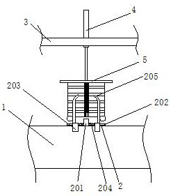
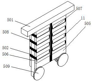
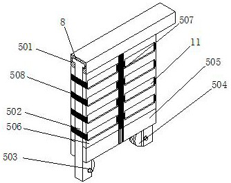
[0041] Example 1: Please refer to Figure 1-5 , an electroplating device for circuit board production, comprising an electroplating tank 1, a transmission mechanism 2, a transmission line 3, a telescopic device 4 and a clamping mechanism 5, the transmission mechanism 2 is arranged on the electroplating tank 1, and the transmission line 3 is arranged on the transmission mechanism 2 Above, telescopic equipment 4 is arranged on conveying line 3, conveying line 3 and telescopic equipment 4 are existing known technologies, do not repeat them here, clamping mechanism 5 is arranged on the drive shaft of telescopic equipment 4, clamping mechanism 5 includes a top plate 501, a side plate 502, a rotating shaft 503 and a clamp ring 504. The top surface of the top plate 501 is fixedly connected with the transmission shaft of the telescopic device 4. The bottom surface of the top plate 501 is provided with a chute 8, and the cross-sectional surface of the chute 8 is convex , the top of the...

Embodiment 2

[0042] Embodiment 2: Please refer to the electroplating tank 6-7 in the figure. On the basis of the first embodiment, a feeding box 6 is arranged on one side of the electroplating tank 1, and the feeding box 6 includes a box body 601, which is also provided on the front side of the box body 601 There is a transmission mechanism 2, and the top surface of the box body 601 is provided with a placement groove 12 on the rear side of the transmission mechanism 2. The back side of the placement groove 12 is provided with a hole and is sleeved with a push rod 602. The push rod 602 is an I-shaped body. The back end of the rod 602 is fixedly connected with a spring B603, and the front end of the spring B603 is fixedly connected with the back of the box body 601. The top surface of the box body 601 is provided with a telescopic slot A13 on both sides of the transmission mechanism 2, and a cylinder is sleeved in the telescopic slot A13. 604, the cylinder 604 is a cylinder with a hollowed-o...

Embodiment 3

[0043] Embodiment 3: Please refer to Figure 8-10 of the electroplating tank. On the basis of Embodiment 2, a dust removal mechanism 7 is arranged in the arrangement hole 11. The dust removal mechanism 7 includes an air bag 701. The air bag 701 is a hollowed-out semi-cylindrical body. The top surface and the bottom surface are respectively fixedly connected with the top surface and the bottom surface of the arrangement hole 11. The bottom end of the back of the airbag 701 is fixedly connected with a slide plate B703, and the top end of the back surface of the airbag 701 is fixedly connected with a slide plate A702. Together, the front of the skateboard A702 is equidistantly provided with ventilation holes A16, and the front of the skateboard B703 is provided with a ventilation hole B17 at the position corresponding to the ventilation hole A16. The height of the ventilation hole B17 is ten times the height of the ventilation hole A16. A through groove B15 is opened, and the throu...


PUM


Abstract

The invention relates to the technical field of electroplating, and discloses an electroplating device for circuit board production, including an electroplating tank, a transmission mechanism, a conveying line, telescopic equipment and a clamping mechanism, the transmission mechanism is arranged on the electroplating tank, and the conveying line is arranged on the transmission mechanism Above, telescopic equipment is set on the conveying line. The clamping mechanism is set on the transmission shaft of the telescopic equipment. The clamping mechanism includes a top plate, a side plate, a rotating shaft and a clamp ring. The top surface of the top plate is fixedly connected with the transmission shaft of the telescopic equipment. The top plate The bottom surface is provided with a chute, the number of side plates is two and both of them are socketed with the chute, and the corresponding surfaces of the two side plates are provided with a through groove A and a movable groove, and a hole is opened on the back of the movable groove and the rotating shaft is socketed in the hole , the front end of the rotating shaft is fixedly connected with a clamp ring. Through the setting of the clamping mechanism, the clamping process of the circuit board before electroplating can be carried out from a low position, which solves the problem that the height of the staff must be affected by the high installation position of the fixture in the existing electroplating device. Certainly asked questions.

Description

technical field [0001] The invention relates to the technical field of electroplating, in particular to an electroplating device for circuit board production. Background technique [0002] After the circuit board is manufactured, in order to protect the thin chemical copper just deposited on the circuit board and prevent the chemical copper from being oxidized and etched by acid, it needs to be added to a certain extent by electroplating. [0003] The existing patent No. CN109898127A proposes an electroplating device for circuit board production, which has the advantage of increasing the adaptability to electroplating of circuit boards of different sizes, but it needs to fix the top of the circuit board with the fixture when it is fixed. This high position fixing method has certain requirements on the height of employees, which affects the factory's work allocation to employees. [0004] The existing patent number CN102080253B proposes an electroplating fixture and a printe...

Claims


Application Information

Patent Timeline
Patent Type & Authority Patents(China)
IPC IPC(8): H05K3/18H05K3/26H05K13/00
CPCH05K3/188H05K3/26H05K13/0069
Inventor 潘烟宁
Owner 台山市图今智控技术有限公司
Why Eureka
Try Eureka