Novel electric multifunctional oral cavity mouth gag

A multi-functional, mouth-opening technology, which is used in stereotaxic surgical instruments, medical science, dentistry, etc., can solve the problems of accurate maintenance of the mouth opening, unable to realize the continuous movement of active and passive opening and closing of the oral cavity at the same time, and achieve accurate maintenance of the mouth opening. , the effect of improving the accuracy of the results and increasing the operability

Pending Publication Date: 2021-01-05
SHANGHAI NINTH PEOPLES HOSPITAL SHANGHAI JIAO TONG UNIV SCHOOL OF MEDICINE
View PDF0 Cites 0 Cited by
  • Summary
  • Abstract
  • Description
  • Claims
  • Application Information

AI Technical Summary

Problems solved by technology

[0005] Aiming at the problems in related technologies, the present invention proposes a new type of electric multifunctional oral mouth gag, which can effectively solve the problem that the prior art cannot simultaneously realize active and passive oral opening-closing continuous movement, maintain precise opening degree, simple operation, and wide application range. question

Method used


Image

  • Novel electric multifunctional oral cavity mouth gag
  • Novel electric multifunctional oral cavity mouth gag
  • Novel electric multifunctional oral cavity mouth gag

Examples


Embodiment 1

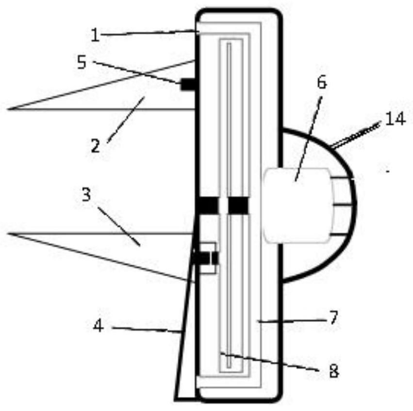
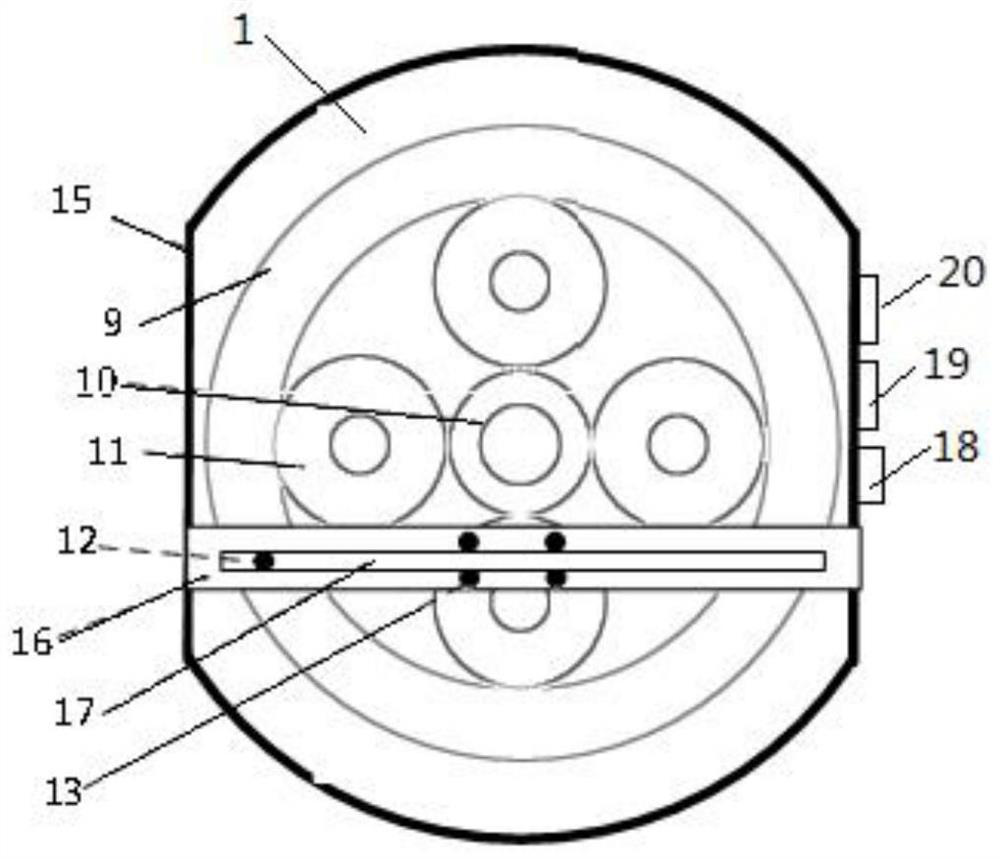
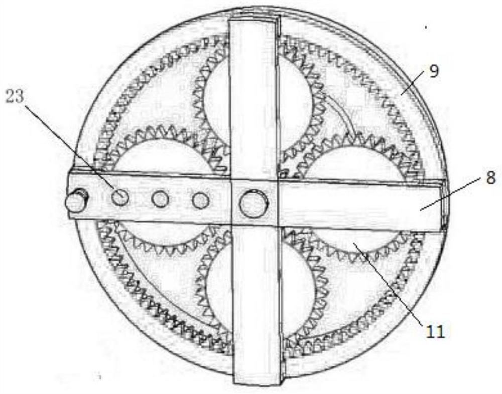
[0030] Such as Figure 1-6 As shown, a new type of electric multifunctional oral mouth opener according to the embodiment of the present invention includes a main body casing 1, the main body casing 1 is divided into a front area and a rear area; A lower support plate 3 is slidably provided in the middle and lower part of the outer side of the front area, and slide rails 15 for installing a slide bar 16 are arranged on both sides of the inner side of the front area, and the lower support plate 3 is detachably mounted on the slide bar 16; A motor 6 is installed in the middle part of the rear area, and a fixed frame 7 is built in the rear area, and the middle part of the fixed frame 7 is provided with a through hole for the transmission shaft of the motor 6 to pass through, and the fixed frame 7 surrounds the through hole for a week A plurality of transmission wheels 11 are provided; a ring gear 9 is arranged on the outer side of the plurality of transmission wheels 11, and a cr...

Embodiment 2

[0033] On the basis of Embodiment 1, the upper support plate 2 is detachably connected to the main body shell 1 through a support plate connecting member 5 . It can be connected on the main body shell 1 or on the fixed frame.

Embodiment 3

[0035] On the basis of Embodiment 1, the slide bar 16 is provided with a slide block 13, and the lower support plate 3 is fixedly connected to the slide block 13 through the support plate connector 5; the slide block moves along the chute 22 The slide block has a slide bar 16 to drive the slide block 13 to move, and the middle part of the slide bar 16 is provided with a bar-shaped block moving track 17, and the block moving track 17 is used for the movement of the block 12.


PUM


Abstract

The invention discloses a novel electric multifunctional oral cavity mouth gag. The mouth gag comprises a main body shell, wherein the main body shell is divided into a front area and a rear area; andan upper supporting plate is arranged at the top of the outer side of the front area, a lower supporting plate is arranged on the middle lower portion of the outer side of the front area in a slidingmode, sliding rails used for sliding rods to be installed are arranged on the two sides of the inner side of the front area, and the lower supporting plate is detachably installed on the sliding rods. The mouth gag has multiple functions, can simultaneously realize active and passive opening-closing continuous movement of an oral cavity and accurate maintenance of the opening degree, and has multiple purposes of auxiliary opening treatment, training rehabilitation, auxiliary maxillofacial repair design and the like; the operation is simple, continuous movement, positioning movement and fixedmaintenance of the oral cavity supporting plates are achieved only by operating a button switch with one hand, the operation time is shortened, and the result precision is improved; and the mouth gagis high in universality, the supporting plates of different sizes or structures can be flexibly replaced according to the characteristics of patient groups, the mouth gag can be used for patients of different groups, and meanwhile the operability of the mouth gag is improved.

Description

technical field [0001] The invention relates to the technical field of medical equipment, in particular to a novel electric multifunctional oral mouth gag. Background technique [0002] In the process of treating oral diseases, mouth gags are commonly used to assist patients in treatment. In addition, in the aspects of oral rehabilitation training, maxillofacial repair design, etc., the mouth gag is also an important and even indispensable medical auxiliary device. [0003] The existing mouth gag technology mainly uses a simple mechanical structure or mechanism to move the upper and lower jaws of the oral cavity to achieve active or passive opening of the oral cavity. Although there are many kinds of oral mouth mouth devices clinically and on the market, they all have one or more of the following disadvantages: the structure is simple, the opening degree is only maintained by wedges, fastening bolts, simple screws, etc., and continuous opening and closing movements cannot b...

Claims


Application Information

Patent Timeline
Patent Type & Authority Applications(China)
IPC IPC(8): A61B90/16A61C19/00
CPCA61C19/00A61B90/16
Inventor 何冬梅王增伟
Owner SHANGHAI NINTH PEOPLES HOSPITAL SHANGHAI JIAO TONG UNIV SCHOOL OF MEDICINE
Why Eureka
Try Eureka