
Cardiac apex implantation cuspid valve clamping device and cardiac apex implantation cuspid valve clamping method

A cusp valve and apex technology, applied in the field of apex implanted cusp valve clamping device, can solve the problems of easy complications, difficult operation, long operation time, etc., reduce side effects, reduce operation difficulty and intensity, and improve operation success rate effect

Inactive Publication Date: 2021-01-05
SHANGHAI HONGYU MEDICAL TECH CO LTD
View PDF0 Cites 4 Cited by
  • Summary
  • Abstract
  • Description
  • Claims
  • Application Information

AI Technical Summary

Problems solved by technology

[0005] The object of the present invention is to provide apical implanted apical valve clamping device and apical implanted apical valve clamping method to solve the problem of using large-size long sheath in the prior art, difficult operation, long operation time and easy to cause complications technical problem

Method used


Image

  • Cardiac apex implantation cuspid valve clamping device and cardiac apex implantation cuspid valve clamping method
  • Cardiac apex implantation cuspid valve clamping device and cardiac apex implantation cuspid valve clamping method
  • Cardiac apex implantation cuspid valve clamping device and cardiac apex implantation cuspid valve clamping method

Examples


Embodiment Construction

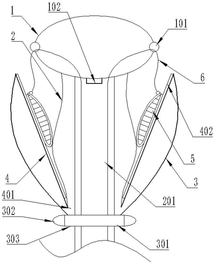
[0057] Embodiments of the technical solutions of the present invention will be described in detail below in conjunction with the accompanying drawings. The following examples are only used to illustrate the technical solutions of the present invention more clearly, and therefore are only examples, rather than limiting the protection scope of the present invention.

[0058] It should be noted that, unless otherwise specified, the technical terms or scientific terms used in this application shall have the usual meanings understood by those skilled in the art to which the present invention belongs.

[0059] The term "proximal end" in the embodiments of the present invention refers to the end of the device that is closer to the user and farther from the implantation site, and the term "distal end" refers to the end of the device that is farther from the user and closer to the implantation site.

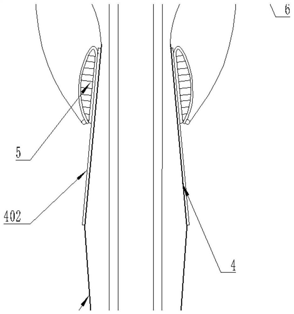
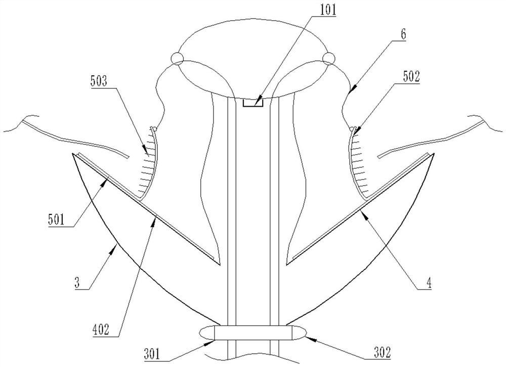
[0060] Such as figure 1 As shown, this embodiment discloses a cusp valve clipping de...


PUM


Abstract

The present invention discloses a cardiac apex implantation cuspid valve clamping device and a cardiac apex implantation cuspid valve clamping method. The cardiac apex implantation cuspid valve clamping device comprises an upper connecting piece, a sealing end piece and a central woven net are sequentially arranged on the upper connecting piece, a rod penetrating cavity is formed in the central woven net, and the upper connecting mechanism is arranged at a near end of the sealing end piece; an inner frame net is connected with a lower end of the central woven net to form an integrated structure; an outer edge of an outer frame net is integrally connected with an outer edge of the inner frame net, besides, a lantern ring is arranged in a middle part of the outer frame net, and a lower connecting mechanism is arranged on an outer ring surface of the lantern ring; elastic clamps are fixed on a surface of the inner frame net; a clamp opening mechanism is used for controlling the elastic clamps to open; an initial memory state of the outer frame net is folding and wrapping the inner frame net and elastic clamps towards a far end. During compression intervention, the cardiac apex implantation cuspid valve clamping device greatly reduces aperture diameter, a small-aperture diameter sheathing canal can be intervened, difficulties and strengths of surgeries are reduced, the large-widthelastic clamps can be used, a capture success rate is increased, the elastic clamps are independently controlled through corresponding pull wires, capture of valve leaflets is easy to control, and universality is strong.

Description

technical field [0001] The invention relates to the technical field of medical devices, in particular to an apex-implanted cusp valve clamping device and a cardiac apex-implanted cusp-valve clamping method. Background technique [0002] With the aging of the population, the incidence of heart valve disease is gradually increasing, followed by the incidence of mitral regurgitation is also showing a rising trend. According to statistics, among heart valve diseases, mitral valve disease accounts for 70% of valve diseases, which accounts for a large proportion. [0003] With the development of science and technology, domestic and foreign device manufacturers have developed a batch of interventional devices for the treatment of mitral valve regurgitation. Among them, Abbott MitraClip and Edward PASCAL are typical representatives. MitraClip was popularized earlier in clinical practice. The mechanical working principle of the clip design is a four-bar linkage structure. The femor...

Claims


Application Information

Patent Timeline
IPC IPC(8): A61F2/24
CPCA61F2/2442A61F2/2454A61F2/246A61F2/2466A61F2210/0014
Inventor 戴宇峰潘炳跃王智杰
Owner SHANGHAI HONGYU MEDICAL TECH CO LTD
Learn More