Balance weight adjusting structure and method for self-walking equipment

A technology for adjusting the structure and self-propelling, which is applied in the directions of vehicle body, body stability, transportation and packaging, etc., which can solve the problems of easy tipping, downward tipping, and backward tipping, etc., so as to prevent the rear wheels from slipping and lower the effect of possibility

Pending Publication Date: 2021-01-05
NANJING SUMEC INTELLIGENT TECH CO LTD
View PDF0 Cites 0 Cited by
  • Summary
  • Abstract
  • Description
  • Claims
  • Application Information

AI Technical Summary

Problems solved by technology

[0004] In order to solve the problem that the self-propelled equipment is easy to fall over when driving on the slope (it is easy to fall backward when going

Method used


Image

  • Balance weight adjusting structure and method for self-walking equipment
  • Balance weight adjusting structure and method for self-walking equipment
  • Balance weight adjusting structure and method for self-walking equipment

Examples


Embodiment 1

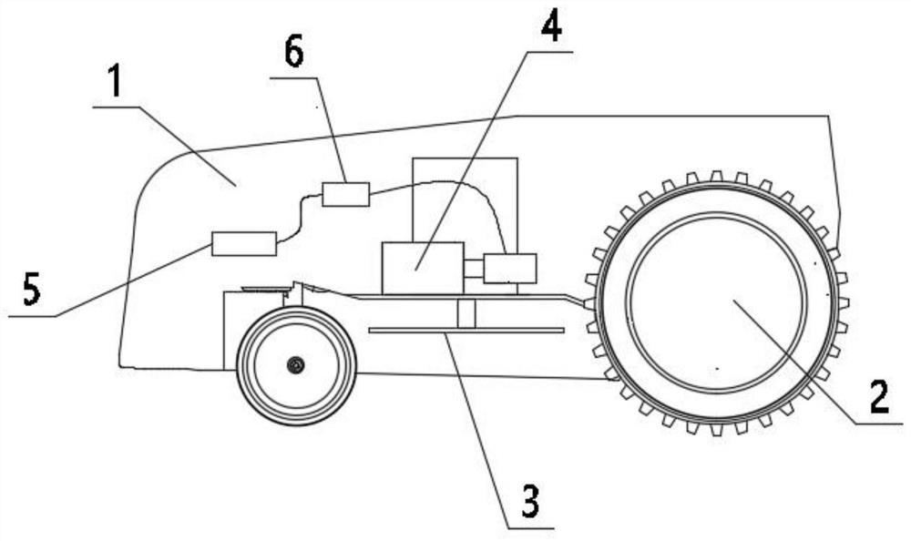
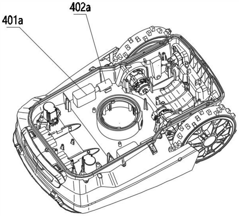
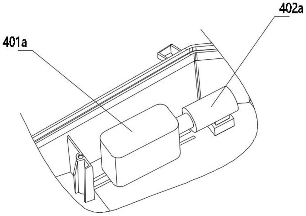
[0039] Such as figure 1 and 2 A lawnmowing robot shown includes a body 1, a drive unit, a cutting unit 3 and a main control unit 6; the drive unit includes a drive wheel 2 driven by a power device. The fuselage 1 is provided with a counterweight adjustment mechanism 4, and the counterweight adjustment mechanism 4 includes a counterweight 401a and a moving part 402a, such as image 3 As shown, the moving part 402a is a hydraulic push rod, which can push the counterweight 401a to move forward and backward. In actual use, when the lawn mowing robot is on a flat road, the counterweight 401a is in the first position, and when the lawn mowing robot is in an uphill state, such as Figure 4 As shown, the counterweight 401a moves to the second position under the drive of the moving part 402a, and the second position is closer to the head of the robot than the first position, so that the center of gravity of the entire lawn mowing robot moves forward, and the center of gravity after t...

Embodiment 2

[0045] Such as Figure 6As shown in the lawn mowing robot, the body 1 is provided with a counterweight adjustment mechanism, the counterweight adjustment mechanism includes a counterweight 401b and a moving part 402c, one end of the counterweight 401b is connected to the body 1, and the moving part 402c is an electric push rod , the counterweight 401b can rotate driven by the moving part 402c, and when the counterweight 401b rotates, the position of its center of gravity changes. Such as Figure 6 As shown, when the mowing robot is on a flat road, the center of gravity of the counterweight 401b is located directly above the rear wheel axis. Such as Figure 7 and 8 As shown, when the mowing robot is on an uphill slope, the counterweight 401b rotates under the push of the moving part 402c, and the center of gravity of the counterweight 401b remains directly above the rear wheel axis.

[0046] The moving parts can also be other structures that can drive objects to rotate, suc...

Embodiment approach

[0052] Such as Figure 6 As shown in the lawn mowing robot, the body 1 is provided with a counterweight adjustment mechanism. The counterweight adjustment mechanism includes a counterweight and moving parts. One end of the counterweight is connected to the body 1. The moving part is an electric push rod. The counterweight can be Driven by the moving parts to rotate, the hinge point of the counterweight and the fuselage 1 is located on the axis of the rear wheel, the counterweight is a symmetrical structure, and its center of gravity is located on the central axis. The counterweight adjustment method based on the above structure is as follows:

[0053] 1. The self-propelled device is equipped with an angle sensor 5 to detect the pitch angle of the fuselage 1;

[0054] 2. When the pitch angle of the self-propelled equipment is 0, the center of gravity of the counterweight is directly above the axis of the rear wheel;

[0055] 3. The moving parts drive the counterweight to rota...


PUM


Abstract

The invention discloses a balance weight adjusting structure and method for self-walking equipment. The balance weight adjusting structure comprises a balance weight adjusting mechanism, the balance weight adjusting mechanism can adjust the gravity center position of equipment according to the pitching angle of a machine body of the self-walking equipment, the balance weight adjusting mechanism comprises a balance weight block, a moving part and an angle sensor, and the position of the balancing weight can be changed under the driving of the moving part. Whether the self-walking equipment is in the uphill and downhill states or not is judged according to the angle numerical value measured by the machine body angle sensor, when the self-walking equipment is in the uphill and downhill states, the balance weight adjusting structure adjusts the gravity center of the whole machine to move forwards by adjusting the position of the balance weight block, and the overturning possibility of theequipment is reduced.

Description

technical field [0001] The invention belongs to the technical field of self-propelled equipment, and in particular relates to a counterweight adjustment structure and method for self-propelled equipment. Background technique [0002] In order to stabilize the fuselage of self-propelled equipment, counterweights are usually set on the fuselage to increase the weight of the whole machine, so that the equipment can run more stably. At the same time, after the self-propelled equipment is equipped with counterweight components, it is necessary to ensure that the center of gravity of the equipment is located at the center of the whole machine to ensure the stable operation of the whole machine and avoid the body from tipping over when running on bumpy and undulating roads. After the counterweight structure is installed and fixed, the center of gravity of the whole machine is fixed. When the self-propelled equipment goes uphill, the horizontal distance between the center of gravity...

Claims


Application Information

Patent Timeline
IPC IPC(8): B62D37/04
CPCB62D37/04
Inventor 成孟哲卢成林周国扬刘楷汪洋王近王夕雯
Owner NANJING SUMEC INTELLIGENT TECH CO LTD
Why Eureka
Try Eureka