
An energy-saving and stable laminated board

A laminated board, stable technology, applied in the direction of floor slabs, buildings, building reinforcements, etc., can solve the problems of weak connection strength, bending and breaking of main bars, etc., to achieve good stability, improve connection stability, and improve stability. Effect

Inactive Publication Date: 2022-03-08
WEIHAI YUQUAN NEW BUILDING MATERIAL
View PDF7 Cites 0 Cited by
  • Summary
  • Abstract
  • Description
  • Claims
  • Application Information

AI Technical Summary

Problems solved by technology

[0004] In view of the related technologies mentioned above, the inventor believes that before the prefabricated floor is poured, several truss reinforcements are generally arranged, and two auxiliary reinforcements are erected on the longitudinal reinforcement. The horizontal reinforcement and the longitudinal reinforcement have a certain deformation force. During the transportation and installation process Among them, the longitudinal reinforcement tends to be bent, and it is difficult to keep all the longitudinal reinforcements on the same horizontal plane, so that some auxiliary reinforcements cannot be in contact with the longitudinal reinforcements, so that the connection strength between the longitudinal reinforcements and the auxiliary reinforcements is weak when the prefabricated floor is cast; During hoisting and transportation, the truss reinforcement is mainly lifted by the spreader to lift the prefabricated floor. If the connection strength between the longitudinal reinforcement and the auxiliary reinforcement is weak, it is easy to cause the main reinforcement of the prefabricated floor to bend or break during hoisting and transportation. The overall connection stability of the prefabricated bottom plate is not good, which will have a negative impact on the subsequent conveying and laminated plate forming

Method used


Image

  • An energy-saving and stable laminated board
  • An energy-saving and stable laminated board
  • An energy-saving and stable laminated board

Examples


Embodiment

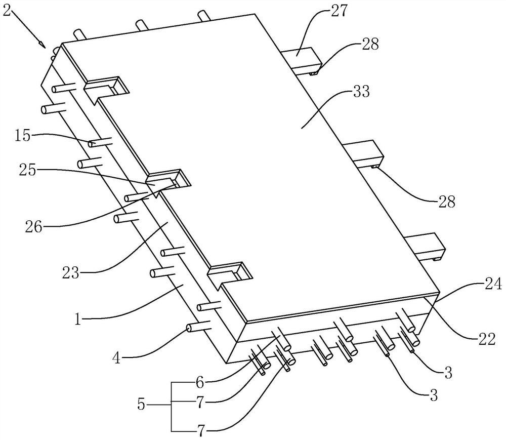
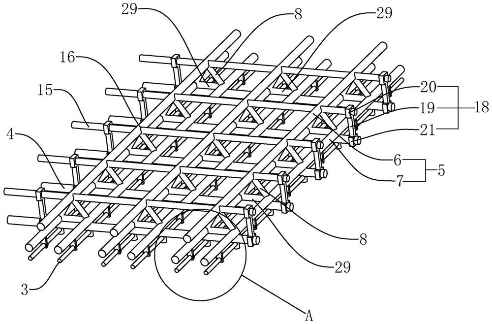
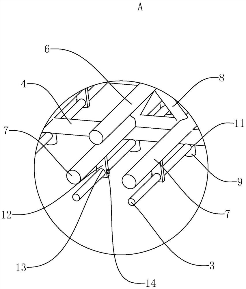
[0035] refer to figure 1 and figure 2 , an energy-saving and stable laminated slab, comprising a prefabricated floor 1 and a cast-in-place reinforced concrete layer 2, the interior of the prefabricated floor 1 is provided with a number of transverse reinforcement bars 3 and longitudinal reinforcement bars 4, the longitudinal reinforcement bars 4 and the transverse reinforcement bars 3 are vertically arranged, and above the longitudinal reinforcement bars 4 There are a number of truss bars 5 parallel to the transverse bars 3. The truss bars 5 include a main bar 6 and two auxiliary bars 7. Several connecting rods 8 are arranged between the main bars 6 and the auxiliary bars 7. The two ends of the connecting bars 8 are connected to the main bar respectively. 6 and the auxiliary reinforcement 7 are fixedly connected, and the main reinforcement 6 of the truss reinforcement 5 and the two auxiliary reinforcement 7 are fixed by the connecting rod 8, so that the overall stability of t...


PUM


Abstract

This application relates to an energy-saving and stable laminated slab, which includes a prefabricated bottom slab and a cast-in-place reinforced concrete layer. There are several transverse and longitudinal reinforcements inside the prefabricated bottom slab, and several truss reinforcements are arranged above the longitudinal reinforcement. The truss reinforcement includes main reinforcement and two Auxiliary reinforcement, several connecting rods are arranged between the main reinforcement and the auxiliary reinforcement. The end of the connecting rod away from the main reinforcement is fixedly connected with a positioning rod. The positioning rod passes through the auxiliary reinforcement and is fixedly connected with the auxiliary reinforcement. The vertical hole matched with the rod, and the lower end of the positioning rod is provided with a horizontal hole matched with the transverse steel bar. The positioning rod passes through the vertical hole on the longitudinal reinforcement, and the transverse reinforcement passes through the horizontal hole on the positioning rod, and the horizontal reinforcement, longitudinal reinforcement and truss reinforcement are connected together through the positioning rod, which improves the stability of the prefabricated floor during casting , thereby improving the stability of the laminated plate after forming.

Description

technical field [0001] The present application relates to the field of construction engineering, in particular to an energy-saving and stable laminated board. Background technique [0002] The laminated slab is an assembled integral floor slab formed by laminating the prefabricated bottom slab and the cast-in-place reinforced concrete layer. The prefabricated bottom slab is not only one of the components of the floor structure, but also a permanent template for the cast-in-place reinforced concrete laminated layer, and horizontal equipment pipelines can be laid in the cast-in-place laminated layer. The laminated slab has good integrity and high rigidity, which can save templates. The upper and lower surfaces of the slab are flat, which is convenient for decoration of the facing layer. It is suitable for high-rise buildings and large-bay buildings that require high overall rigidity. In the actual construction process, it is usually necessary to lay several groups of laminate...

Claims


Application Information

Patent Timeline
Patent Type & Authority Patents(China)
IPC IPC(8): E04B5/17E04C5/01E04C5/16
CPCE04B5/17E04C5/01E04C5/16
Inventor 杨治军王德波侯军生王翔宇
Owner WEIHAI YUQUAN NEW BUILDING MATERIAL
Learn More