Identification card edge detection method and device and storage medium
A technology of edge detection and card identification, which is applied in the field of image processing, can solve problems such as misjudgment and calculation efficiency, and achieve the effect of improving edge detection efficiency, small detection error, and reduced calculation amount
Pending Publication Date: 2021-01-05
PING AN TECH (SHENZHEN) CO LTD
0 Cites 1 Cited by
AI-Extracted Technical Summary
Problems solved by technology
[0005] In view of this, the embodiment of the present application provides a card edge detection method, device and storage medium to ...
Method used
Further, by combining the card edge detection method provided by the embodiment of Fig. 4 with the embodiment of Fig. 1, the card edge detection of each video frame in each target video is realized. After the video frame of the card, the key point tracking of the video frame can be carried out based on the card edge detection method provided by the embodiment of Figure 1. If the key point tracking is always successful, it will always enter the key point tracking cycle provided by the embodiment of Figure 1 , to achieve high-precision and efficient card edge detection; if the key point tracking fails, that is, when the target video does not contain a card, it usually means that the card in the target video needs to be replaced. At this time, it is provided by the embodiment in Figure 4 The edge detection method of the card directly detects the edge of the card. The end-to-end edge detection model can also support real-time and efficient card edge detection, and after obtaining the updated edge of the card, enter Figure 1 again. The key point tracking cycle of the embodiment; this is repeated until the card edge detection result of each video frame in the target video is obtained, which realizes the efficient and high-precision detection of the target video, and can be applied to the real-time detection of the card of the mobile terminal.
In the method provided by the present embodiment, by carrying out fitting processing to a plurality of target line segments, obtain the edge straig...
Abstract
The invention is suitable for the technical field of graphic processing, and provides an identification card edge detection method and device, and a storage medium. The method comprises the steps of obtaining a to-be-processed target frame in a target video; according to the position of the target frame, obtaining first key point information of an adjacent frame adjacent to the target frame, and the first key point information comprising corner point information of the identification card; inputting the first key point information and the target frame into a preset key point position trackingmodel to obtain second key point information of the target frame and judgment information of the target frame, the judgment information being used for representing whether the target frame contains anidentification card or not; and determining a first identification card detection result of the target frame according to the second key point information and the judgment information. The identification card edge detection method provided by the embodiment of the invention is less influenced by the complex background and/or fuzzy edge of the to-be-detected video frame, and the detection error issmall. The invention also relates to the field of digital medical treatment, and is used for quickly identifying patient identity documents.
Application Domain
Image analysisCharacter and pattern recognition +2
Technology Topic
Computer visionPatient identification +3
Image
Examples
- Experimental program(1)
Example Embodiment
[0034]In the following description, for the purpose of illustration rather than limitation, specific details such as a specific system structure and technology are proposed for a thorough understanding of the embodiments of the present application. However, it should be clear to those skilled in the art that the present application can also be implemented in other embodiments without these specific details. In other cases, detailed descriptions of well-known systems, devices, circuits, and methods are omitted to avoid unnecessary details from obstructing the description of this application.
[0035]The reference to "one embodiment" or "some embodiments" described in the specification of this application means that one or more embodiments of this application include a specific feature, structure, or characteristic described in combination with the embodiment. Therefore, the words "in one embodiment", "in some embodiments", "in some other embodiments", "in some other embodiments", etc. appearing in different places in this specification are not necessarily All refer to the same embodiment, but mean "one or more but not all embodiments", unless otherwise specifically emphasized. The terms "including", "including", "having" and their variations all mean "including but not limited to", unless otherwise specifically emphasized in other ways.
[0036]The technical solutions of the present application and how the technical solutions of the present application solve the above technical problems are exemplified below with specific embodiments. It is worth noting that the specific embodiments listed below can be combined with each other, and the same or similar concepts or processes may not be repeated in some embodiments.
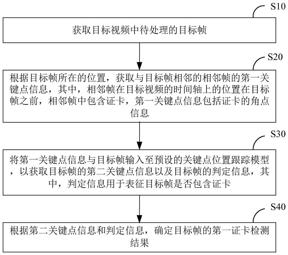
[0037]figure 1 This is a schematic flow chart of the card edge detection method provided by an embodiment of this application, which is suitable for execution in a terminal device or a server, such asfigure 1 As shown, the method includes:
[0038]S10. Obtain a target frame to be processed in the target video.
[0039]In this embodiment, the target video includes M consecutive video frames, which are the first frame, the second frame...the Mth frame, the target frame can be any frame in the target video, and M is an integer greater than 1.
[0040]S20. Obtain first key point information of adjacent frames adjacent to the target frame according to the position of the target frame, where the position of the adjacent frame on the time axis of the target video is before the target frame, and the adjacent frames include For the card, the first key point information includes the corner point information of the card.
[0041]In this embodiment, the position of the target frame may refer to the position of the target frame in the target video after being sorted according to the playback time.
[0042]For example, the position of the target frame on the time axis of the target video.
[0043]Exemplarily, the target video includes M video frames, and the M video frames are sorted according to the playback time as the first frame, the second frame...the Mth frame, and the first frame is the first frame of the target video.
[0044]If the target frame is the jth frame, the adjacent frame is the j-1th frame, where j is an integer greater than 1 and less than or equal to M.
[0045]It can be understood that if there are adjacent frames in the target frame, the target frame is not the first frame of the target video.
[0046]In this embodiment, the ID card may refer to various cards such as an ID card, a social security card, and a bank card, which is not specifically limited here.
[0047]In this embodiment, when the adjacent frame contains a card (hereinafter referred to as the first card), the first key point information of the adjacent frame may include the corner point coordinates of the card.
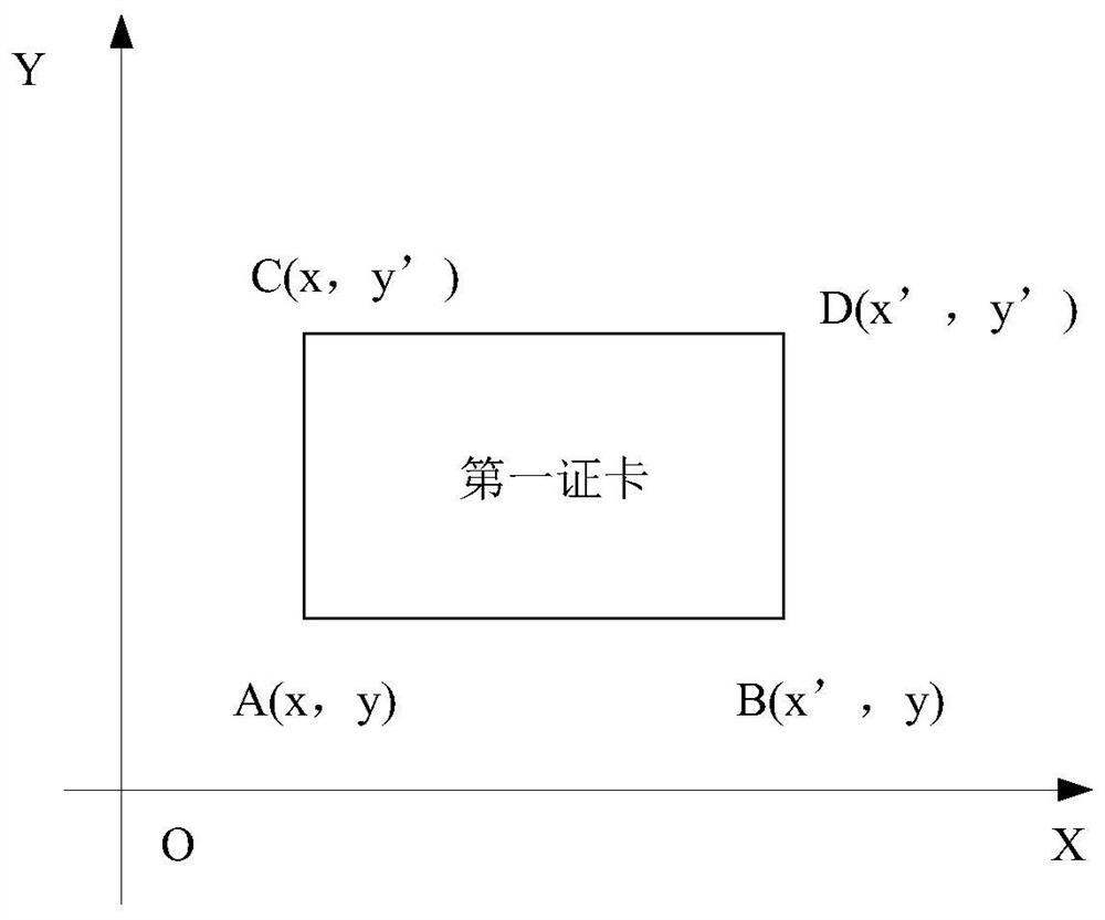
[0048]Illustratively, please refer tofigure 2 ,figure 2 This is a schematic diagram of the first card provided in an embodiment of this application. Such asfigure 2 As shown, the first card is in the XOY coordinate system, which is the coordinate system of the adjacent frame.
[0049]The key point information of the first card includes the coordinates of the four corner points of the first card, namelyfigure 2 The corner coordinates of the four corners of ABCD. After obtaining the four corner coordinates of the first card, the length and width of the first card and the straight line parameters of the four edge lines of the first card can be calculated according to the four corner coordinates.
[0050]S30. Input the first key point information and the target frame into a preset key point position tracking model to obtain the second key point information of the target frame and the determination information of the target frame; the determination information is used to characterize whether the target frame contains a card.
[0051]In this embodiment, the preset key point position tracking model may be a pre-trained active contour model. The input of the keypoint position tracking model is the initial contour (initial edge information) and the target frame, and then iterates step by step based on the initial contour, updating the target frame containing the contour of the object until the preset conditions are reached.
[0052]Among them, the initial contour can be confirmed according to the first key point information. The preset condition may be the preset number of iterations or the iteration error is less than the preset value, etc., which is not specifically limited here.
[0053]In this embodiment, the key point position tracking model may include an input layer, two convolution layers (the first convolution layer Conv1 and the second convolution layer Conv2), a classifier, and an output layer.
[0054]Among them, the composition network structure of the first convolutional layer Conv1 and the second convolutional layer Conv2 may be the same.
[0055]For example, in order to improve processing efficiency, both the first convolution layer Conv1 and the second convolution layer Conv2 include a convolution layer, a BN layer, and an activation function, and the size of the convolution kernel is 3*3.
[0056]In this embodiment, the key point position tracking model can output the classification result and the convolution result in parallel.
[0057]Wherein, the classification result may refer to determination information that characterizes whether the target frame contains a card, and the convolution result may be used to calculate the second key point information of the target frame.
[0058]In this embodiment, the second key point information may include the target frame including corner coordinates of the object.
[0059]S40. Determine the first card detection result of the target frame according to the second key point information and the determination information.
[0060]In this embodiment, the first card detection result may include whether it contains the mark information of the card, and the edge information of the card when the target frame contains the card.
[0061]Among them, the edge information includes the parameters of the edge line and the corner coordinates.
[0062]For example, it can be determined whether the target frame contains a card based on the determination information. In the case where the determination information indicates that the target frame contains a card, it can be determined based on the second key point information that the target frame contains edge information of the card. In the case that the ID card is not included, the generated target frame does not include the ID of the ID card.
[0063]In this embodiment, after the first card detection result of the target frame is determined, the next frame of the target video can be obtained continuously, where the next frame is the target video adjacent to the target frame and the playback time is later than the aforementioned target frame Video frames.
[0064]Taking the above-mentioned next frame as the updated target frame, the steps of this embodiment are repeated until the card detection result of each video frame contained in the target video is obtained.
[0065]According to the card edge detection method provided by the embodiment of the present application, the first key point information of the adjacent frame adjacent to the target frame is obtained according to the position of the target frame, because the adjacent frame is the time axis of the target video The position of the above is in the video frame before the target frame, and the adjacent frame contains the card, so the first key point information of the adjacent frame can be used as the initial constraint position of the key point of the target frame, and then according to the first key point of the adjacent frame The information performs key point tracking processing (key point position tracking model prediction) to obtain the second key point information of the target frame, and the first card detection result of the target frame is determined according to the second key point; compared with the prior art directly based on The edge detection algorithm determines that the target frame contains the edge information of the object. The card edge detection method provided by this application is less affected by the complex background and/or blurred edges of the video frame, the detection error is small, and the key point tracking model does not require Performing feature point matching processing greatly reduces the amount of calculation, improves the efficiency of edge detection, and is suitable for the real-time detection requirements of card coding of mobile terminals.
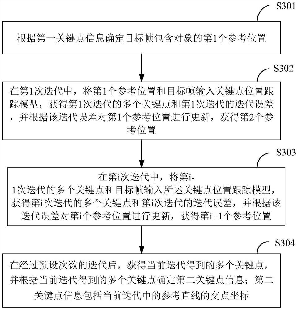
[0066]image 3 This is a schematic diagram of the process for obtaining second key point information provided by an embodiment of this application, which describesfigure 1 In the embodiment, S30 is a possible implementation manner for acquiring the second key point information of the target frame, such asimage 3 As shown, inputting the first key point information and the target frame into the key point position tracking model to obtain the second key point information of the target frame includes:
[0067]S301: Determine, according to the first key point information, the first reference position where the target frame contains the object.
[0068]In this embodiment, the first parameter position is used to determine that the target frame contains the initial edge information of the object.
[0069]For example, the first reference position may include the coordinates of a corner point of the card, the length of the card, and the width of the card, and the initial edge information may be an edge straight line calculated according to the first reference position.
[0070]In this embodiment, the first key point information includes the corner point coordinates of the first card. According to the first key point information, it is determined that the target frame contains the first reference position of the object. Coordinates, determine the edge information of the first card, including any corner coordinates, the length of the first card, and the width of the first card. The edge information of the first card is determined as the first card in the target frame. Reference positions.
[0071]Illustratively, please refer tofigure 2 , The first key point information includes the four corner coordinates of ABCD of the first card: A(x,y), B(x',y), C(x,y') and D(x',y) '), the first reference position can be expressed as G1(x, y, w, h), where (x, y) represents the coordinates of the corner point A in the lower left corner of the first card, w represents the length of the first card, which is equal to x'-x, and h represents The width of the first card is equal to y'-y.
[0072]S302. In the first iteration, input the first reference position and the target frame into the key point position tracking model, obtain multiple key points of the first iteration and the iteration error of the first iteration, and compare the results according to the iteration error. The first reference position is updated, and the second reference position is obtained.
[0073]S303. In the i-th iteration, input multiple key points and target frames of the i-1th iteration into the key-point position tracking model to obtain multiple key points of the i-th iteration and the i-th iteration. Error, and update the i-th reference position according to the iterative error to obtain the i+1-th reference position; where i is an integer greater than 1.
[0074]In this embodiment, if i is 1, the first reference position is determined by the first key point information, and the multiple key points of the first iteration are located on the first reference line, and the first reference line includes Determined edge straight line; if i is an integer greater than 1, the i-th reference position is determined according to the result of the i-1th iteration, and multiple key points of the i-th iteration are located on the second reference straight line. The second reference straight line contains The straight line of the edge determined by the i-th reference position.
[0075]In this embodiment, multiple key points and the iteration error of this iteration are obtained in each iteration.
[0076]Among them, the input in the first iteration is the first reference position and the target frame, and the input of the i-th iteration is the multiple key points and the target frame of the i-1th iteration.
[0077]In this embodiment, in the first iteration, the first reference position and the target frame are input into the key point position tracking model to obtain multiple key points X of the first iteration1And the iteration error delta_1 of the first iteration, and according to the iteration error delta_1, the first reference position G1Update to get the second reference position G2(x2, Y2, W, h).
[0078]Wherein, the multiple key points of the first iteration are located on the first reference straight line, and the first reference straight line includes the edge straight line determined according to the first reference position.
[0079]Exemplarily, in the first iteration, the first reference straight line is determined according to the first reference position. Specifically, the first reference straight line includes the 4 edge straight lines represented by the first reference position, that is, the 4 edges of the first card. Edge straight line; correspondingly, multiple key points obtained in the first iteration are evenly distributed on the four edge straight lines of the first card.
[0080]In this embodiment, in the i-th iteration, the positions and target frames of multiple key points of the i-1th iteration are input into the key-point position tracking model to obtain multiple key points X of the i-th iterationiAnd the iteration error delta_i of the i-th iteration, and according to the iteration error delta_i, the i-th reference position is updated to obtain the i+1-th reference position; where i is an integer greater than 1.
[0081]Among them, the multiple key points of the i-th iteration are located on the second reference straight line, and the second reference straight line includes the edge straight line determined according to the i-th reference position;
[0082]Exemplarily, in i iterations, the i-th reference position can be expressed as Gi(xi, Yi, W, h), then the second reference line of the i-th iteration contains according to GiDetermine the four edge straight lines, correspondingly, the i-th iteration obtains multiple key points XiEvenly distributed according to GiDetermine the four edges on a straight line.
[0083]In this embodiment, in order to obtain multiple key points located on the reference straight line (first reference straight line or second reference straight line) in each iteration, when the key point position tracking model is pre-trained, the result of each prediction is Strong constraints are added to the key points, so that the key points of each prediction are points located on four edge straight lines, which specifically refer to the four edge straight lines of a rectangular card.
[0084]S304. After a preset number of iterations, obtain multiple key points obtained in the current iteration, and determine second key point information according to the multiple key points obtained in the current iteration; the second key point information includes the reference straight line in the current iteration The coordinates of the intersection point.
[0085]In this embodiment, the termination condition of the iteration is the number of iterations. After a preset number of iterations, the second key point information is obtained by terminating the iteration, where the preset number can be preset by the user.
[0086]For example, if the preset number of times is 4, the second key point information may include the fourth reference position, G4(x4, Y4, W, h).
[0087]In this embodiment, after the key point tracking model obtains multiple key points of the current iteration, the coordinates of the multiple key points are input to the classifier, and the classifier determines whether the target frame contains the card according to the coordinates of the multiple key points, and generates the corresponding The judgment information.
[0088]Exemplarily, in order to explain this embodiment more clearly, please refer to the following embodiments together. In this embodiment, the preset number of times is 3, and the first reference position can be expressed as G1(x, y, w, h), the key point tracking model is expressed as evolve_gcn.
[0089]Step 1. In the first iteration, according to G1(x, y, w, h) and the target frame, initializing to obtain multiple initial key points of the first iteration, you can pass X0Indicates, specifically X0You can refer to formula (1):
[0090]
[0091]Among them, n represents the number of key points, (pn,qn) Is the coordinate of the n-th initial key point.
[0092]In this step, according to G1Initialize to get X0, Can refer to G1Perform linear interpolation between the determined four corner points to obtain X0.
[0093]For example, please refer tofigure 2 , Perform uniform sampling on the boundary line between corner point A and corner point B to obtain 128 key points. Same as above, perform uniform sampling on the other three boundary lines to obtain a total of 512 key points.
[0094]In this step, after obtaining X0Then run the evolve_gcn model to get the iterative error delta_1 of the first iteration.
[0095]Step 2. Update the coordinates of the key points according to the iteration error of the first iteration, and obtain multiple key points of the first iteration, denoted as X1; Where X1=X0+delta_1.
[0096]In this step, at the same time according to the iteration error delta_1 of the first iteration, the first reference position G1Update, get G2.
[0097]Step 3. In the second iteration, the multiple key points of the first iteration X2And the target frame as input, run the key point tracking model evolve_gcn, get the iterative error delta_2 of the second iteration.
[0098]Step 4. Update the coordinates of the key points according to the iteration error delta_2 of the second iteration to obtain multiple key points of the second iteration, denoted as X2; Where X2=X1+delta_2, X2The multiple key points in G2Determine the 4 straight lines.
[0099]In this step, at the same time according to the iteration error delta_1 of the second iteration, the second reference position G2Update, get G3.
[0100]Step 5. In the third iteration, the multiple key points of the second iteration X2And the target frame as input, run the key point tracking model evolve_gcn, get the iterative error delta_3 of the third iteration.
[0101]Step 6. Update the coordinates of the key points according to the iteration error delta_3 of the third iteration to obtain multiple key points of the third iteration, denoted as X3; Where X3=X2+delta_3.
[0102]Step 7. According to X3Determine the second key point information of the target frame, and determine whether the target frame contains a card.
[0103]In practical applications, when the following situations occur, key point tracking processing cannot be performed based on the first key point information of adjacent frames:
[0104]One is that the target frame is the first frame of the target video frame, and the target frame has no adjacent frames at this time;
[0105]The second is that although the target frame is not the first frame of the target video frame, but its adjacent frame does not contain a card, the first key point information of the adjacent frame cannot be obtained at this time.
[0106]When the above situation occurs, in order to determine the card edge information of the target frame, it is necessary to perform edge detection processing on the target frame to obtain the card edge detection result of the target frame. In order to ensure the accuracy of card edge detection and meet the real-time processing requirements of mobile terminals, the card edge detection of the target frame is performed based on the end-to-end edge detection model in this application.Figure 4 The embodiments are illustrated as examples.
[0107]Figure 4 This is a schematic flow chart of a card edge detection method provided by another embodiment of this application, such asFigure 4 As shown, after acquiring the target frame to be processed in the target video, the card edge detection method further includes:
[0108]S50: When the target frame is the first frame of the target video, or the adjacent frame does not contain a card, preprocess the target frame to obtain a grayscale image of the target frame.
[0109]In this embodiment, the first frame of the target video refers to the video frame with the earliest playing time in the target video.
[0110]Among them, the size of the gray image is smaller than the size of the target frame.
[0111]In this embodiment, after the target frame is scaled to the target size, binarization processing is performed on the scaled target frame to obtain a grayscale image of the target frame.
[0112]For example, the target frame is a color picture with a size of 1080*1090. Preprocessing the target frame may mean that the target frame is first scaled to an image with a size of 128*256, and then the above image is binarized to obtain the corresponding gray Degree image.
[0113]The purpose of this step is to scale and binarize the target frame, so as to reduce the amount of data processing for edge detection in subsequent steps and improve the efficiency of edge detection.
[0114]S60. Input the gray image to an edge detection model to obtain third key point information of the gray image; the edge detection model is an end-to-end neural network model, and the third key point information includes multiple edge line parameters of the gray image.
[0115]The purpose of this embodiment is to detect the edge of the card. Based on the edges of the card are all straight lines, the edge detection model in this embodiment adds linear regression processing after sampling the grayscale image, by adding linear constraints , Directly output the parameters of the straight edge, realize the end-to-end edge detection of the image.
[0116]In this embodiment, the edge detection model includes an encoder, a decoder, and a linear regression sub-model connected in sequence.
[0117]Among them, the encoder is used to obtain multiple local features of the grayscale image, and classify the pixel values of the grayscale image according to the multiple local features to obtain local pixel values corresponding to different elements; the elements include edge lines.
[0118]For example, the encoder may be a lightweight convolutional neural network to meet the application requirements of mobile terminals with limited computing power. Illustratively, the encoder may be a shuffle Net network model.
[0119]Among them, the decoder is used to match the classified local pixel values with the pixels of the grayscale image. Specifically, the decoder is used to perform up-sampling processing on the reduced feature map, and perform convolution processing on the up-sampling processed image to make up for the loss of detail caused by the reduction of the image by the pooling layer in the encoder.
[0120]Among them, the linear regression sub-model is used to determine multiple edge line parameters according to the pixel points of the matching edge line. The optimal solution of the linear regression sub-model satisfies the weighted least squares method.
[0121]For example, the input of the linear regression sub-model can be expressed as input, and the size of the input is 4*128*256, which contains 4 feature maps with a size of 128*256, which correspond to 4 straight lines whose classification features are "edges".
[0122]For each 128*256 feature map W, a linear constraint function y=ax+b is added, that is, each pixel map on the feature map satisfies the above constraint function. Based on this, the following formula is obtained:
[0123]W*[Y_map,1]=A*W*X_map (2)
[0124]Among them, W represents the feature map, X_map represents the x-axis coordinates of the pixels on the feature map to form the sub-feature map, Y_map represents the y-axis coordinates of the pixels on the feature map to form the sub-feature map, and V contains Represents the straight line parameters of the linear constraint function.
[0125]Based on formula (2), the calculation formula of the linear parameter V can be referred to formula (3):
[0126]V=inv{(T(Y_map)*Y_map)*T(X_map)*X_map)} (3)
[0127]Among them, T(Y_map) represents the transposition of Y_map, T(X_map) represents the transposition of X_map, and inv represents inverse processing.
[0128]Based on the weighted least squares method, the value of V is calculated. Since the input has 4 feature maps, 4 straight line parameters can be obtained.
[0129]S70. Determine the second card detection result of the target frame according to the third key point information.
[0130]In this embodiment, the third key point information includes a plurality of edge line parameters of the gray image, and the shape of the object contained in the gray image can be determined according to the plurality of edge line parameters.
[0131]In the case that multiple edge line parameters determine a rectangle, it can be determined that the object contained in the gray image is a card, and the corner coordinates of the card are determined according to the above multiple edge line parameters, and then the target frame contains The corner coordinates of the card.
[0132]When multiple edge line parameters determine that the object is not a rectangle, it can be determined that the object contained in the grayscale image is not a card, and the generated target frame does not contain the marking information of the card.
[0133]The card edge detection method provided in this embodiment is suitable for the case where the target frame is the first frame of the target video, or the adjacent frames do not contain a card. The method first obtains a grayscale image according to the target frame and inputs the grayscale image The edge detection model reduces the amount of data processing for edge detection and improves the efficiency of edge detection; and the edge detection model in this embodiment is an end-to-end neural network model, and the result of training/prediction is directly multiple edges of grayscale images The linear parameters, while improving the detection speed, the fitting effect is better than the segmented processing method in the prior art (the method in the background art).
[0134]Further, by addingFigure 4 Example andfigure 1 The card edge detection methods provided in the embodiments are combined to realize the card edge detection of each video frame in each target video. After the video frame containing the card is acquired for the first time, it can be based onfigure 1 The card edge detection method provided by the embodiment performs the key point tracking of the video frame. If the key point tracking has been successful, it will always enterfigure 1 The key point tracking loop provided in the embodiment realizes high-precision and efficient card edge detection; if the key point tracking fails, that is, if the target video does not contain the card, it usually means that the card is replaced in the target video. Pass at this timeFigure 4 The card edge detection method provided by the embodiment directly performs the edge detection of the card. The end-to-end edge detection model can also support real-time and efficient card edge detection. After obtaining the updated edge of the card, the edge detection is performed again. enterfigure 1 The key point tracking loop of the embodiment is repeated until the card edge detection result of each video frame in the target video is obtained, which achieves high-efficiency and high-precision detection of the target video, which can be applied to the real-time detection of the card of the mobile terminal.
[0135]In this embodiment, after the corner coordinates of the target frame containing the card are obtained, the edge information of the target frame containing the card can be directly calculated according to the corner coordinates. Since the target frame is reduced before entering the edge detection model, the corner coordinates of the gray image are obtained and then enlarged. After zooming in to the original image, the edge of the target frame may have errors. In order to improve the accuracy of edge detection, After the grayscale image is enlarged and the target frame contains the edge of the card, the edge can be corrected to improve the accuracy of the edge detection of the target frame.Figure 5 withFigure 6 The embodiments are illustrated as examples.
[0136]Figure 5 The schematic diagram of the process for determining the detection result of the second card provided by an embodiment of this application describesFigure 4 A possible implementation of S70 in the embodiment, such asFigure 5 As shown, according to the third key point information, determining the second card detection result of the target frame includes:
[0137]S701. In a case where a rectangle can be determined by multiple edge line parameters, determine multiple corner point coordinates of the card to be detected according to the multiple edge line parameters; the card to be detected is a card included in the target frame.
[0138]In this embodiment, when multiple edge line parameters determine a rectangle, it can be determined that the grayscale image contains a card, that is, the target frame contains a card, and the card contained in the target frame may be a card to be detected.
[0139]In this embodiment, it is determined that the gray image contains the corner point coordinates of the card according to multiple edge line parameters, and then the corner coordinates are enlarged according to a preset ratio to obtain multiple corner point coordinates of the card to be detected.
[0140]Among them, the preset ratio isFigure 4 The reduction ratio when preprocessing the target frame in the embodiment.
[0141]It is understandable that the card to be detected contains 4 corner points, and the coordinates of the 4 corner points of the card to be detected can be obtained in this step.
[0142]S702: According to the coordinates of the multiple corner points, intercept multiple edge regions of the card to be detected, and the multiple edge regions correspond to the multiple corner points one-to-one.
[0143]In this embodiment, the region of interest corresponding to each corner point is determined according to the coordinates of multiple corner points, and the region of interest is intercepted to obtain multiple edge regions corresponding to the multiple corner points one-to-one.
[0144]Among them, the region of interest refers to the region to be processed obtained by intercepting the target frame in the form of a box, a circle, an ellipse, and an irregular polygon. In this embodiment, a block can be used for interception.
[0145]S703. Determine the edge line corresponding to each edge area, and determine the edge line as the edge line of the card to be detected.
[0146]In this embodiment, the method of determining the edge line corresponding to each edge area is the same.
[0147]For example, multiple sub-regions can be obtained by partitioning an edge region, and after determining the target line segment corresponding to each sub-region, fitting processing is performed on the multiple target line segments to obtain the edge straight line corresponding to the above-mentioned one edge region.
[0148]Among them, the target line segment is the edge line segment of the sub-region.
[0149]In the method provided in this embodiment, by fitting multiple target line segments to obtain the edge line corresponding to the edge region, the error caused by the image scaling process can be effectively reduced, and the accuracy of the edge line corresponding to the edge region is improved, and thus Improve the accuracy of the edge line of the card to be detected.
[0150]Figure 6 The schematic diagram of the process of determining the edge straight line corresponding to each edge region provided by an embodiment of this application describesFigure 5 A possible implementation of S703 in the embodiment, such asFigure 6 As shown, determine the edge line corresponding to each edge area, including:
[0151]S7031. Perform edge detection on the first edge area to obtain an edge image of the first edge area along the first direction; the first edge area is any one of the multiple edge areas, and the first direction is the edge of any edge of the card to be detected direction.
[0152]The edge is composed of pixels whose pixel values undergo transitions (gradient changes) in the image. Based on this characteristic, the edge detection of the first edge region can be performed according to the Sobel operator.
[0153]Among them, the Sobel operator contains two sets of 3x3 matrices, namely X-direction matrix and Y-direction matrix. The two sets of matrices are respectively subjected to planar convolution processing with the image of the first edge region, and the first edge region can be obtained respectively. Approximate gradients in the X and Y directions, so that the edges of the first edge region in the X and Y directions can be obtained.
[0154]In this embodiment, the first direction is the direction of any edge of the card to be detected, and the constituent elements of the card to be detected include content and edges.
[0155]In one embodiment, since the planar image has convolution processing in the X direction (left and right) and Y direction (up and down), the first edge area can be determined according to the position of the first edge area relative to the content in the card to be detected. direction.
[0156]For example, when the first edge area is located on the left and right sides of the card content to be detected, the first direction is the Y direction, and when the first edge area is located on the upper and lower sides of the card content to be detected, the first direction is the X direction.
[0157]In another embodiment, the first direction is the preset direction. In order to obtain the edge straight line of the first edge region, the first edge region may be inverted first, and then the first edge region that has been inverted in the first direction. The edge area undergoes planar convolution processing.
[0158]Among them, flip includes horizontal flip and vertical flip.
[0159]Exemplary, please refer toFigure 7 ,Figure 7 A schematic diagram of the first edge area and the first direction is provided for this embodiment of the application. Such asFigure 7 As shown, the first edge area is a rectangular area selected based on a dashed box. The first edge area can be any one of the four edge areas of the card to be detected, and can be any one of ①, ②, ③, and ④.
[0160]In this example, the first direction is the Y direction, and the Sobel operator is determined to be the Y direction matrix. In order to make the content of the card to be detected in the edge image after planar convolution processing is always located on the right side of the first edge area, the first edge area may be flipped.
[0161]If the first edge area is ①, the first edge area is directly subjected to planar convolution processing based on the Y-direction matrix to obtain the edge image of the first edge area along the Y direction, and the content of the card to be detected is located in the first The right side of the edge area.
[0162]If the first edge area is ②, first flip the first edge area horizontally, and then perform planar convolution processing on the flipped first edge area based on the Y-direction matrix to obtain the edge image of the first edge area along the Y direction At this time, the content of the card to be detected is also located on the right side of the first edge area.
[0163]If the first edge area is ③, firstly flip the first edge area clockwise and vertically, and then perform planar convolution processing on the flipped first edge area based on the Y-direction matrix to obtain the Y-direction of the first edge area Edge image. At this time, the content of the card to be detected is also located on the right side of the first edge area.
[0164]If the first edge area is ④, firstly flip the first edge area counterclockwise and vertically, and then perform planar convolution processing on the flipped first edge area based on the Y-direction matrix to obtain the Y-direction of the first edge area Edge image. At this time, the content of the card to be detected is also located on the right side of the first edge area.
[0165]It should be understood that if the preset first direction is different, the turning direction is different; similarly, if the relative position between the content of the card to be detected and the edge line is different, the turning direction is different.
[0166]In this step, edge detection is performed on the first edge area to obtain an edge image of the first edge area along the first direction, and the relative position of the content of the card to be detected in the edge image and the target edge is fixed.
[0167]S7032. Divide the edge image into N sub-images and perform binarization processing on each sub-image to obtain N binarized sub-images; where N is an integer greater than 1.
[0168]In this embodiment, the edge image can be equally divided into N sub-images.
[0169]In this embodiment, each sub-image can be adaptively binarized based on the Otsu method to obtain corresponding N binarized sub-images.
[0170]S7033. Perform straight line detection on N binarized sub-images, and obtain N target straight lines and 2N end points of the N target straight lines; where the target straight line is the line closest to the edge of the target in the binarized sub-image, and the target The edge is determined according to the first direction.
[0171]In this embodiment, for each sub-image of the N binarized sub-images, the sub-images are subjected to line detection processing to obtain multiple straight lines contained in the sub-image, and the straight line that is closest to the target edge among the multiple straight lines Determine the target line.
[0172]Wherein, the target edge is the edge closest to the content of the card to be detected in the sub-image, which can be determined according to the first direction.
[0173]Illustratively, please refer toFigure 8 ,Figure 8 A schematic diagram of the sub-image provided by an embodiment of this application, such asFigure 8 As shown, after the straight line detection processing, the two straight line segments contained in the sub-image can be obtained, which are Z1(PQ) and Z2(RS). In the edge image after planar convolution processing in this example, the content of the card to be detected is always on the right side of the first edge area, soFigure 8 The target edge is Z3.
[0174]byFigure 8 It can be seen that in the two straight line segments, Z2(RS) Distance to target edge Z3If the distance is closer, you can determine Z in the two straight line segments2(RS) is the target straight line, and then the two endpoints R and S of the target straight line are obtained.
[0175]Performing the processing of this step on the N sub-images in the first edge region can obtain 2N endpoints.
[0176]S7034. Perform straight line fitting on the 2N endpoints to obtain an edge straight line corresponding to the first edge region.
[0177]In this embodiment, the straight line fitting process can be performed based on the ransac algorithm.
[0178]The method for determining the edge line corresponding to each edge area provided by the embodiment of the application is to perform partition processing on each edge area, and after obtaining the target line of each edge area, fitting is performed according to the multiple end points of the target line Processing to obtain the edge line corresponding to the edge area can effectively reduce the error caused by the image scaling process, improve the accuracy of the edge line corresponding to the edge area, and further improve the accuracy of the edge line of the card to be detected.
[0179]The lightweight convolutional neural network model in the prior art, such as the ShuffleNet network model, usually includes a channel confusion layer to achieve the calculation amount of a multi-channel image. In this embodiment, the image input to the edge detection model is a gray-scale image, which is not required To perform channel shuffling, in order to further increase the computational complexity of data calculation, the network structure of the ShuffleNet network model in the prior art is further optimized in the embodiment of the present application.
[0180]The card edge detection method, equipment and storage medium of the present invention can be used for medical data processing, which helps to improve the efficiency, safety or stability of medical data processing. Used for rapid identification of patient ID.
[0181]Picture 9 This is a schematic diagram of the network structure of an encoder provided by an embodiment of this application, such asPicture 9 As shown, each network node of the encoder includes a first branch and a second branch that are operated in parallel. Among them, the first branch includes a sequentially connected average pooling layer, a 1*1 convolutional layer, and an up-sampling layer, and the second branch includes a 1*1 convolutional layer.
[0182]In this embodiment, the first branch is used to extract local features of grayscale images, and the second branch is used to extract global features of grayscale images. After the local features are obtained, the global features are connected through the connection layer, and the The processing result is used as the input of the decoder. Specifically, the connection layer can be implemented based on the Concat function.
[0183]In this embodiment, the average pooling layer in the first branch is used to down-sampling the grayscale image and transfer the scale-invariant features to the next layer (ie 1*1 convolutional layer), 1*1 convolution The layer is used to obtain the local features of the incoming feature map,Picture 9 BN mainly realizes the normalization of the distribution of images to accelerate learning.
[0184]The up-sampling layer in the first branch may perform up-sampling processing based on the bilinear interpolation method.
[0185]The network structure of the encoder provided in the embodiments of the present application streamlines the encoder of the lightweight convolutional neural network in the prior art, removes the channel confusion layer, further reduces the computational complexity of the edge detection model, and improves the performance of the edge detection model. The calculation speed is to meet the real-time processing of the edge detection of the mobile terminal.
[0186]It should be understood that the size of the sequence number of each step in the foregoing embodiment does not mean the order of execution. The execution sequence of each process should be determined by its function and internal logic, and should not constitute any limitation on the implementation process of the embodiment of the present application.
[0187]Based on the card edge detection method provided in the foregoing embodiment, the embodiment of the present invention further provides an embodiment of an apparatus for implementing the foregoing method embodiment.
[0188]Picture 10 This is a schematic structural diagram of a card edge detection device provided by an embodiment of this application. Such asPicture 10 As shown, the card edge detection device 80 includes a first acquisition module 801, a second acquisition module 802, a position tracking module 803, and a first determination module 804, where:
[0189]The first obtaining module 801 is configured to obtain a target frame to be processed in a target video;
[0190]The second acquiring module 802 is configured to acquire first key point information of adjacent frames adjacent to the target frame according to the location of the target frame, wherein the adjacent frame is at the time of the target video The position on the axis is before the target frame, the adjacent frames include a card, and the first key point information includes corner point information of the card;
[0191]The position tracking module 803 is configured to input the first key point information and the target frame into a preset key point position tracking model to obtain the second key point information of the target frame and the determination of the target frame Information, wherein the determination information is used to characterize whether the target frame contains a card;
[0192]The first determining module 804 is configured to determine the first card detection result of the target frame according to the second key point information and the determination information.
[0193]Optionally, the position tracking module 803 inputs the first key point information and the target frame into the key point position tracking model to obtain the second key point information of the target frame, which specifically includes:
[0194]Determine, according to the first key point information, that the target frame contains the first reference position of the object;
[0195]In the first iteration, the first reference position and target frame are input into the key point position tracking model, and multiple key points of the first iteration and the iteration error of the first iteration are obtained, and the first iteration error is calculated based on the iteration error. Update the two reference positions to obtain the second reference position; the multiple key points of the first iteration are located on the first reference line, and the first reference line includes the edge line determined according to the first reference position;
[0196]In the i-th iteration, input multiple key points and target frames of the i-1th iteration into the key-point position tracking model to obtain multiple key points of the i-th iteration and the iteration error of the i-th iteration, And update the i-th reference position according to the iteration error to obtain the i+1-th reference position; where i is an integer greater than 1, and multiple key points of the i-th iteration are located on the second reference straight line, and the second The reference straight line includes the edge straight line determined according to the i-th reference position;
[0197]After a preset number of iterations, multiple key points obtained in the current iteration are obtained, and the second key point information is determined according to the multiple key points obtained in the current iteration; the second key point information includes the intersection of the reference straight lines in the current iteration coordinate.
[0198]Optionally, the first determining module 804 determines the card detection result of the target frame according to the second key point information and the determination information, which specifically includes:
[0199]In the case where the determination information indicates that the target frame contains the card, it is determined according to the second key point information that the target frame contains the edge information of the card; the edge information includes the parameters of the edge line and the corner coordinates.
[0200]Picture 11 This is a schematic structural diagram of a card edge detection device provided by another embodiment of this application. Such asPicture 11 As shown, the card edge detection device 80 further includes a preprocessing module 805, an edge detection module 806, and a second determination module 807;
[0201]The preprocessing module 805 is used to preprocess the target frame to obtain the grayscale image of the target frame when the target frame is the first frame of the target video or the adjacent frame does not contain a card; the size of the grayscale image Less than the size of the target frame.
[0202]The edge detection module 806 is used to input the gray image into the edge detection model to obtain the third key point information of the gray image; the edge detection model is an end-to-end neural network model, and the third key point information includes multiple gray images Edge line parameters.
[0203]The second determination module 807 is configured to determine the second card detection result of the target frame according to the third key point information.
[0204]Optionally, the second determination module 807 determines the second card detection result of the target frame according to the third key point information, which specifically includes:
[0205]In the case that multiple edge line parameters can determine a rectangle, determine multiple corner point coordinates of the card to be detected according to the multiple edge line parameters; the card to be detected is the card contained in the target frame;
[0206]According to the coordinates of multiple corner points, intercept multiple edge areas of the card to be detected, and the multiple edge areas correspond to multiple corner points one-to-one;
[0207]Determine the edge line corresponding to each edge area, and determine the edge line as the edge line of the card to be detected.
[0208]Optionally, the second determining module 807 determines the edge line corresponding to each edge region, which specifically includes:
[0209]Perform edge detection on the first edge area to obtain an edge image of the first edge area along the first direction; the first edge area is any one of the plurality of edge areas, and the first direction is any one of the cards to be detected The direction of the edge
[0210]Divide the edge image into N sub-images and perform binarization processing on each sub-image to obtain N binarized sub-images; where N is an integer greater than 1;
[0211]Perform straight line detection on N binarized sub-images to obtain N target straight lines and 2N end points of the N target straight lines; among them, the target straight line is the line with the closest distance to the target edge in the binarized sub-image, and the target edge is based on The first direction is determined;
[0212]Perform straight-line fitting on 2N endpoints to obtain the edge straight line corresponding to the first edge region.
[0213]Optionally, the edge detection model is a lightweight convolutional neural network; the edge detection model includes: an encoder, a decoder, and a linear regression sub-model connected in sequence;
[0214]Among them, the encoder is used to obtain a variety of local features of the grayscale image, and classify the pixel values of the grayscale image according to the multiple local features to obtain the local pixel values corresponding to different elements; the elements include edge lines;
[0215]The decoder is used to match the local pixel value with the pixel point of the gray image;
[0216]The linear regression sub-model is used to determine multiple edge line parameters according to the pixels of the matching edge line;
[0217]Among them, the optimal solution of the linear regression model satisfies the weighted least squares method.
[0218]Optionally, the network node of the encoder includes a first branch and a second branch of parallel operation;
[0219]Among them, the first branch includes a sequentially connected average pooling layer, a 1*1 convolutional layer, and an up-sampling layer, and the second branch includes a 1*1 convolutional layer.
[0220]Picture 10 withPicture 11 The card edge detection device provided in the illustrated embodiment can be used to implement the technical solutions in the foregoing method embodiments, and its implementation principles and technical effects are similar, and will not be repeated here in this embodiment.
[0221]Picture 12It is a schematic diagram of a card edge detection device provided by an embodiment of the present application. Such asPicture 12As shown, the card edge detection device 90 includes: at least one processor 901, a memory 902, and a computer program that is stored in the memory 902 and can run on the processor 901. The card edge detection device further includes a communication component 903, wherein the processor 901, the memory 902, and the communication component 903 are connected by a bus 904.
[0222]When the processor 901 executes the computer program, the steps in the foregoing embodiments of the card edge detection method are implemented, for example,figure 1 Steps S10 to S40 in the illustrated embodiment. Or, when the processor 901 executes the computer program, the function of each module/unit in the foregoing device embodiments is realized, for example,Picture 10 The functions of modules 801 to 804 are shown.
[0223]Exemplarily, the computer program may be divided into one or more modules/units, and the one or more modules/units are stored in the memory 902 and executed by the processor 901 to complete the application. One or more modules/units may be a series of computer program instruction segments capable of completing specific functions, and the instruction segments are used to describe the execution process of the computer program in the card edge detection device 90.
[0224]Those skilled in the art can understand,Picture 12It is only an example of the card edge detection device, and does not constitute a limitation on the card edge detection device. It can include more or less components than shown in the figure, or a combination of certain components, or different components, such as input and output devices , Network access equipment, bus, etc.
[0225]The card edge detection device in the embodiment of the application may be a mobile terminal, including but not limited to a smart phone, a tablet computer, a personal digital assistant, an e-book, etc.
[0226]The card edge detection device can also be a terminal device, a server, etc., which is not specifically limited here.
[0227]The so-called processor 901 can be a central processing unit (Central ProcesskngUnkt, CPU), other general-purpose processors, digital signal processors (DkgktalSkgnal Processor, DSP), application-specific integrated circuits (ApplkcatkonSpeckfkfkcKntegratedCkrcukt, ASKC), ready-made programmable gate arrays (Fkeld-ProgrammableGate Array, FPGA) or other programmable logic devices, discrete gates or transistor logic devices, discrete hardware components, etc. The general-purpose processor may be a microprocessor or the processor may also be any conventional processor or the like.
[0228]The memory 902 can be an internal storage unit of the card edge detection device, or an external storage device of the card edge detection device, such as a plug-in hard disk, a smart memory card (Smart Medka Card, SMC), and a secure digital (Secure Dkgktal, SD) card, flash card (Flash Card), etc. The memory 902 is used to store the computer program and other programs and data required by the card edge detection device. The memory 902 can also be used to temporarily store data that has been output or will be output.
[0229]The bus may be an industry standard architecture (Kndustry Standard Archktecture, KSA) bus, an external device interconnection (Perkpheral Component, PCK) bus, or an extended industry standard architecture (Extended Kndustry Standard Archktecture, EKSA) bus. The bus can be divided into address bus, data bus, control bus, etc. For ease of representation, the buses in the drawings of this application are not limited to only one bus or one type of bus.
[0230]The embodiments of the present application also provide a computer-readable storage medium, where the computer-readable storage medium stores a computer program, and when the computer program is executed by a processor, the steps in the foregoing method embodiments can be realized.
[0231]The embodiments of the present application provide a computer program product. When the computer program product runs on the card edge detection device, the card edge detection device can realize the steps in the foregoing method embodiments when executed.
[0232]If the integrated unit is implemented in the form of a software functional unit and sold or used as an independent product, it can be stored in a computer readable storage medium. Based on this understanding, this application implements all or part of the processes in the above-mentioned embodiments and methods, and can be completed by instructing relevant hardware through a computer program. The computer program can be stored in a computer-readable storage medium, and the computer program is being processed. When the device is executed, the steps of the foregoing method embodiments can be implemented. Among them, the computer program includes computer program code, and the computer program code may be in the form of source code, object code, executable file, or some intermediate forms. The computer-readable medium may include at least any entity or device capable of carrying the computer program code to the photographing device/terminal device, recording medium, computer memory, read-only memory (ROM, Read-Only Memory), random access memory (RAM) , Random Access Memory), electric carrier signal, telecommunications signal and software distribution medium. Such as U disk, mobile hard disk, floppy disk or CD-ROM, etc. In some jurisdictions, according to legislation and patent practices, computer-readable media cannot be electrical carrier signals and telecommunication signals.
[0233]In the above-mentioned embodiments, the description of each embodiment has its own emphasis. For parts that are not detailed or recorded in an embodiment, reference may be made to related descriptions of other embodiments.
[0234]A person of ordinary skill in the art may realize that the units and algorithm steps of the examples described in combination with the embodiments disclosed herein can be implemented by electronic hardware, or a combination of computer software and electronic hardware. Whether these functions are executed by hardware or software depends on the specific application and design constraint conditions of the technical solution. Professionals and technicians can use different methods for each specific application to implement the described functions, but such implementation should not be considered beyond the scope of this application.
[0235]In the embodiments provided in this application, it should be understood that the disclosed apparatus/network equipment and method may be implemented in other ways. For example, the device/network device embodiments described above are only illustrative. For example, the division of modules or units is only a logical function division, and there may be other divisions in actual implementation, such as multiple units or components. Can be combined or integrated into another system, or some features can be omitted or not implemented. In addition, the displayed or discussed mutual coupling or direct coupling or communication connection may be indirect coupling or communication connection through some interfaces, devices or units, and may be in electrical, mechanical or other forms.
[0236]The units described as separate components may or may not be physically separate, and the components displayed as units may or may not be physical units, that is, they may be located in one place, or they may be distributed on multiple network units. Some or all of the units may be selected according to actual needs to achieve the objectives of the solutions of the embodiments.
[0237]The above embodiments are only used to illustrate the technical solutions of the application, not to limit them; although the application has been described in detail with reference to the foregoing embodiments, a person of ordinary skill in the art should understand that: The recorded technical solutions are modified, or some of the technical features are equivalently replaced; these modifications or replacements do not cause the essence of the corresponding technical solutions to deviate from the spirit and scope of the technical solutions of the embodiments of this application, and should be included in this application Within the scope of protection.
PUM


Description & Claims & Application Information
We can also present the details of the Description, Claims and Application information to help users get a comprehensive understanding of the technical details of the patent, such as background art, summary of invention, brief description of drawings, description of embodiments, and other original content. On the other hand, users can also determine the specific scope of protection of the technology through the list of claims; as well as understand the changes in the life cycle of the technology with the presentation of the patent timeline. Login to view more.
Similar technology patents
Parking lot column detection method and device, vehicle and storage medium
Owner:GUANGZHOU XIAOPENG CONNECTIVITY TECH CO LTD
Car trunk seal ring matching surface detection device and method based on real working condition simulation
Owner:JIANGSU RUNMO AUTOMOBILE TESTING EQUIP
Multi-stage sorting equipment for cone crusher steel castings and using method of multi-stage sorting equipment
Owner:禹州明旭铸业科技有限公司
Risk application detection method and device and server
Owner:INDUSTRIAL AND COMMERCIAL BANK OF CHINA
Classification and recommendation of technical efficacy words
- Reduce detection error
- small amount of calculation
Threaded hole detection equipment
Owner:YUANTAI AUTOMATION TECH SUZHOU
Displacement measurement device
Owner:PANASONIC INTELLECTUAL PROPERTY MANAGEMENT CO LTD
Color recognition based quantitative measurement method for concentration of to-be-measured liquid
Owner:SHENZHEN ZAITIANYIFANG SCI & TECH LTD
Real-time regression detection system and method for solid rocket propellant burning surface
Owner:UNIV OF SHANGHAI FOR SCI & TECH
License plate detection method based on deep learning
Owner:CHENGDU XINEDGE TECH
Vehicle path planning method based on storage unmanned vehicle
Owner:NANJING UNIV OF SCI & TECH
Phase interferometer direction finding method for ambiguity resolution by extension baselines
Owner:UNIV OF ELECTRONIC SCI & TECH OF CHINA
Motion noise interference eliminating method suitable for wearable heart rate monitoring device
Owner:BEIJING UNIV OF POSTS & TELECOMM