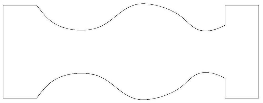
A stone cutting method processed into special-shaped stone pillars
A stone cutting and stone technology, which is applied in the field of stone cutting processed into special-shaped stone columns, can solve the problems of inability to form edges and corners, end gaps of special-shaped stone columns, defects of special-shaped stone columns, etc., and achieve the effect of a simple cutting method.
- Summary
- Abstract
- Description
- Claims
- Application Information
AI Technical Summary
Problems solved by technology
Method used
Image

Examples
Embodiment 1
[0048] The stone cutting method sequentially includes the following steps:
[0049] Step A1: The cutting piece is moved to the upper side of the upper end edge of the cutting piece, and then the cutting piece is moved along the axis of the stone material and toward the first direction, and continues to cut from the upper end of the stone material; The direction is taken as an example from top to bottom.
[0050] Step A2: When the cutting piece is cut to gradually approach the lower edge of the stone, the cutting piece is moved horizontally outward to leave the surface of the stone, so that a certain distance is formed between the cutting piece and the outer surface of the stone;
[0051] During the cutting process from top to bottom, the cutting piece gradually approaches the lower end edge of the stone, which means that after the cutting piece continues to cut, its cutting surface leaves the stone surface and no longer contacts, and the cutting piece is idling, that is, after...
Embodiment 2
[0057] The difference between this embodiment and the first embodiment is that the cutting member reciprocates up and down to cut the stone.
[0058] In this embodiment, the stone cutting method includes the following steps in turn:
[0059] Step A1: The cutting piece moves to the upper side of the upper end edge of the cutting piece, and then the cutting piece moves along the axis of the stone material and toward the first direction, and continues to cut from the upper end edge of the stone material; The first direction is the top-to-bottom direction as an example for description;
[0060] Step A2: When the cutting piece is cut to gradually approaching the lower end edge of the stone, the cutting piece moves horizontally outward to leave the surface of the stone, so that a certain distance is formed between the cutting piece and the outer surface of the stone;
[0061] Step A3: The cutting piece moves downward until the cutting piece is located at the lower side of the lower...
Embodiment 3
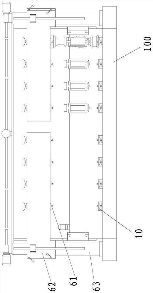
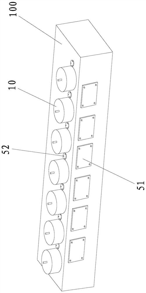
[0067] like Figure 3-4 As shown, there are multiple rotating bottom brackets 10 in the aforementioned stone fixture, and each rotating bottom bracket 10 is arranged at intervals on the upper side of the work box 100. Installed in the work box 100 .
[0068] Specifically, the station rotation mechanism (that is, the aforementioned rotary drive mechanism) is installed inside the work box 100 . The work box 100 is in the shape of a rectangular parallelepiped. The work box 100 is divided into a plurality of stations at intervals along its length direction. The work box 100 Corresponding to the upper side of each station, a rotating bottom bracket 10 is installed in a rotatable manner, wherein the number of the stations is set according to the number of cutting devices on the machine table.
[0069] Further, the work box 100 includes a bottom plate, a left side plate, a right side plate, a front side plate, a rear side plate and an upper side plate that are jointly connected to f...
PUM
 Abstract
Description
Claims
Application Information