Air conditioner with humidifying function

An air-conditioning and functional technology, applied in air-conditioning systems, air humidification systems, heating methods, etc., can solve the problems of inconvenient maintenance and air conditioners without humidification function, and achieve easy maintenance, quick disassembly and assembly, and simple overall structure Effect

Inactive Publication Date: 2021-01-08
陕西钧诚建鑫机电工程有限公司
View PDF2 Cites 0 Cited by
  • Summary
  • Abstract
  • Description
  • Claims
  • Application Information

AI Technical Summary

Problems solved by technology

[0006] The purpose of the present invention is to solve the problem that the air conditioner in the prior art does not have a good humidification function, and the humidification component is installed inside the air conditioner, which makes it very inconvenient to overhaul and maintain, and cannot well meet the actual use needs. A kind of air conditioner with humidification function

Method used


Image

  • Air conditioner with humidifying function
  • Air conditioner with humidifying function
  • Air conditioner with humidifying function

Examples


Embodiment 1

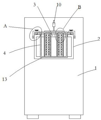
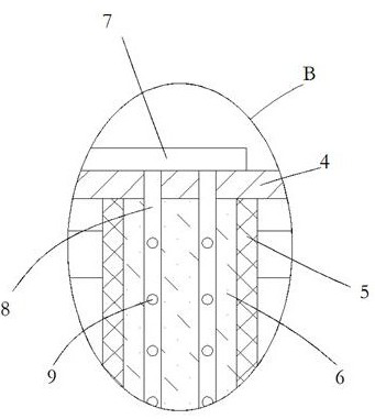
[0024] Example 1 as Figure 1-3 As shown, this air conditioner with humidification function includes an air conditioner body 1 and an air outlet shell 2 installed on the front side of the air conditioner body 1. A socket 3 is opened on the upper side of the air outlet shell 2 and a fixed frame is movably inserted into the socket. 4. The upper and lower opposite sides of the fixed frame 4 are symmetrically fixed with a plurality of breathable mesh frames 5, and the breathable mesh frame 5 is fixed with a water-absorbent cloth 6, and the upper end of the fixed frame 4 is fixed with a buffer tube 7, and the buffer tube 7 The lower end is evenly fixed and communicated with a plurality of humidification pipes 8. The lower pipe wall of the humidification pipe 8 extends through the body into the fixed frame 4 and is inserted into the inner side of the absorbent cloth 6. The side wall of the humidification pipe 8 is evenly opened with a plurality of permeation holes. 9. The upper side...

Embodiment 2

[0025] Embodiment 2 is on the basis of embodiment 1 such as figure 1 As shown, the bottom inner wall of its air outlet shell 2 is provided with a slot 13 for inserting the fixed frame 4 .

Embodiment 3

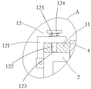
[0026] Embodiment 3 is such as on the basis of embodiment 1 figure 2 As shown, its clamping mechanism 12 includes an L-shaped crimping plate 121 rotatably connected to the upper side wall of the air outlet shell 2. The L-shaped crimping plate 121 is crimped on the upper side of the positioning plate 11. The L-shaped crimping plate 121 The horizontal portion of the horizontal part is provided with a socket and a clamping rod 122 is movable in the socket. The surface of the positioning plate 11 is provided with a clamping hole 123 corresponding to the clamping rod 122. The upper end of the clamping rod 122 is fixedly connected with a The reset pull plate 124 , the lower end of the reset pull plate 124 and the upper end of the L-shaped crimping plate 121 are fixedly connected with the same clamping spring 125 sleeved outside the clamping rod 122 .


PUM


Abstract

The invention relates to the technical field of air conditioners, and discloses an air conditioner with a humidifying function. The air conditioner comprises an air conditioner body and an air outletshell arranged on the front side of the air conditioner body, wherein an inserting opening is formed in the upper side of the air outlet shell, and a fixing frame is movably inserted into the inserting opening; a plurality of breathable net frames are symmetrically and fixedly arranged on the inner walls of the upper and lower opposite sides of the fixing frame; water absorption cloth is fixedly arranged in the breathable net frames; a buffer pipe is fixedly arranged at the upper end of the fixing frame; the lower end of the buffer pipe uniformly and fixedly communicates with a plurality of humidifying pipes; lower side pipe wall penetrating bodies of the humidifying pipes extend into the fixing frame and are inserted into the inner side of the water absorption cloth; a plurality of permeation holes are uniformly formed in the side walls of the humidifying pipes; a micro-pump machine is fixedly arranged on the side wall of the upper side of the air conditioner body; and a water outletof the micro-pump machine communicates with the buffer pipe through a water outlet pipe. The air conditioner has a good humidifying function, the overall structure is simple, and a humidifying assembly is arranged outside the air conditioner body and is convenient to overhaul, maintain and use.

Description

technical field [0001] The invention relates to the technical field of air conditioners, in particular to an air conditioner with a humidification function. Background technique [0002] Air conditioner means air conditioner. Refers to the equipment that uses manual means to adjust and control the temperature, humidity, flow rate and other parameters of the ambient air in a building or structure. [0003] In the patent authorization announcement number CN 204786968 U, a patent with a humidification function is proposed, which is characterized in that it includes: a fan; a cooling device; an air flow duct, one end of the air flow duct is connected to the air outlet of the fan, The other end of the air flow duct is connected to the air inlet of the cooling device; a cooling duct, one end of the cooling duct is connected to the air outlet of the cooling device, and the other end of the cooling duct extends into the space to be cooled; A fixed bracket, one end of the fixed bra...

Claims


Application Information

Patent Timeline
Patent Type & Authority Applications(China)
IPC IPC(8): F24F5/00F24F6/04F24F11/89F24F13/20F24F110/20
CPCF24F5/0003F24F6/04F24F13/20F24F11/89F24F2110/20Y02B30/54
Inventor 苟涛涛
Owner 陕西钧诚建鑫机电工程有限公司
Why Eureka
Try Eureka