
Optical imaging lens

An optical imaging lens and imaging technology, applied in the field of optical imaging, can solve the problems of lens brightness decrease, increase the effective focal length of optical imaging lens, etc., and achieve the effect of increasing imaging quality

Pending Publication Date: 2021-01-08
GENIUS ELECTRONICS OPTICAL XIAMEN
View PDF2 Cites 0 Cited by
  • Summary
  • Abstract
  • Description
  • Claims
  • Application Information

AI Technical Summary

Problems solved by technology

[0003] However, when the focal length of the optical imaging lens is increased, the aperture value also increases, causing the overall brightness of the lens to decrease. Therefore, how to increase the effective focal length of the optical imaging lens while maintaining the imaging quality and maintaining the aperture value is the same as the manufacturing yield. Topics that need to be explored in depth

Method used


Image

  • Optical imaging lens
  • Optical imaging lens
  • Optical imaging lens

Examples


Embodiment Construction

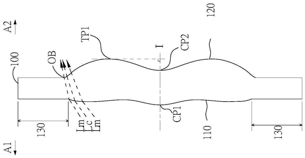
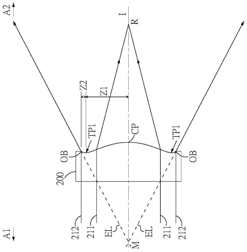
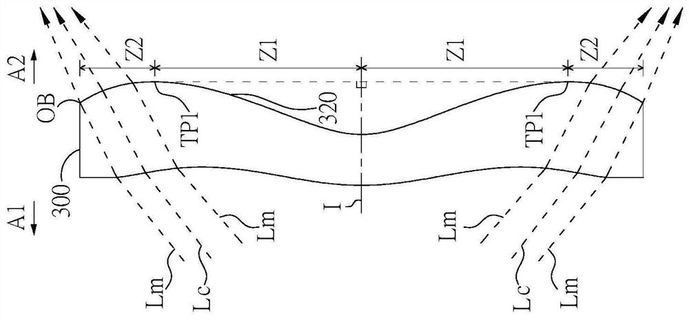
[0080] Before starting to describe the present invention in detail, at first clearly represent the symbol explanation in the accompanying drawings: 1, 2, 3, 4, 5, 6, 7, 8, 9, 10 optical imaging lens; 100, 200, 300, 400, 500 , L1, L2, L3, L4, L5 lens; 110, 410, 510, L1A1, L2A1, L3A1, L4A1, L5A1, TFA1, TF2A1 object side; 120, 320, L1A2, L2A2, L3A2, L4A2, L5A2, TFA2, TF2A2 image side; 130 assembly part; 211, 212 parallel rays; A1 object side; A2 image side; CP center point; CP1 first center point; CP2 second center point; TP1 first transformation point; TP2 second transformation point; OB optical boundary; I, I1 optical axis; I2 second optical axis; Lc chief ray; Lm marginal ray; EL extension line; Z3 relay area; M, R intersection point; Z1, L1A1C, L1A2C, L2A1C, L2A2C, L3A1C , L3A2C, L4A1C, L4A2C, L5A1C, L5A2C optical axis area; Z2, L1A1P, L1A2P, L2A1P, L2A2P, L3A1P, L3A2P, L4A1P, L4A2P, L5A1P, L5A2P circumferential area; STO aperture; TF filter; IMA imaging surface; RL reflecti...


PUM


Abstract

The invention provides an optical imaging lens. The optical imaging lens sequentially comprises a first lens, a second lens, a third lens, a fourth lens and a fifth lens from an object side to an image side. By means of controlling the concave-convex curved surface arrangement of the surfaces of the five lenses, the optical imaging lens achieves the purposes of increasing the effective focal length, maintaining the aperture value and having good imaging quality.

Description

technical field [0001] The invention relates to the field of optical imaging, in particular to an optical imaging lens. Background technique [0002] The specifications of portable electronic products are changing with each passing day, and its key components - optical imaging lenses are also becoming more diversified. The scope of application is not limited to shooting images and videos, but also needs to be telephoto. The optical zoom function can be achieved by combining the telephoto lens with the wide-angle lens; the longer the effective focal length of the telephoto lens, the higher the magnification of the optical zoom. [0003] However, when the focal length of the optical imaging lens is increased, the aperture value also increases, causing the overall brightness of the lens to decrease. Therefore, how to increase the effective focal length of the optical imaging lens while maintaining the imaging quality and maintaining the aperture value is the same as the manufac...

Claims


Application Information

Patent Timeline
IPC IPC(8): G02B13/00G02B13/18
CPCG02B13/0015G02B13/0045G02B9/60G02B13/0065G02B13/02G02B13/007H04N23/55G02B27/0025
Inventor 廖华滨董传博林海谢宏健
Owner GENIUS ELECTRONICS OPTICAL XIAMEN
Learn More