Industrial display screen connecting wire winding mechanism

A technology for display screens and connecting wires, which is applied in the direction of instruments, electrical digital data processing, digital data processing components, etc., and can solve problems such as messiness, inconvenient installation of display screen connecting wires, and long connecting wires of display screens.

Inactive Publication Date: 2021-01-08
西安德创自动化工程有限公司
View PDF3 Cites 0 Cited by
  • Summary
  • Abstract
  • Description
  • Claims
  • Application Information

AI Technical Summary

Problems solved by technology

[0003] In view of this, Chinese Patent No. CN210836045U proposes an industrial display screen, which is completely embedded and installed on the top step of the front shell through the touch screen, and its height is flush with the height of the side wall of the front shell 1 so that the structure of the industrial display screen is compact. It is very convenient to disassemble and install. Chinese Patent No. CN210253497U proposes a dust-proof device on the industrial display screen, which can prevent dust on the display screen and reduce dust adhesion on the display screen when workers do not operate the display screen. The effect of quantity effect, Chinese Patent No. CN211191090U proposes an industrial display screen that is easy to clean. Through the setting of the fixed block, the installation and disassembly of the heat dissipation mechanism become more convenient. At the same time, through the cooperation of the connecting mechanism and the fixed block, it can The entire heat dissipation mechanism is stably installed in the rear shell, and in the above patents, the connection wires of the industrial LCD display are not wound, which makes the connection wires of the display screen long and messy, which is inconvenient for the display screen connection wires installation

Method used


Image

  • Industrial display screen connecting wire winding mechanism
  • Industrial display screen connecting wire winding mechanism
  • Industrial display screen connecting wire winding mechanism

Examples


Embodiment 1

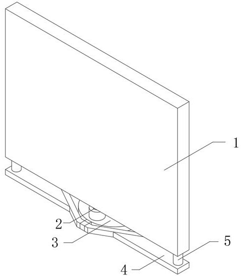
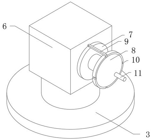
[0021]Example 1Figure 1-2 As shown, the display screen body 1 is included. One side of the display screen body 1 is fixed with a fixed block 6, one side of the fixed block 6 is rotated with a first turntable 7, and one side of the first turntable 7 is rotated by a rotating shaft with a second Two turntables 8, one side of the outer wall of the first turntable 7 is hingedly provided with a connecting rod 9, and the outer wall of the second turntable 8 is fixed with a fixing ring, and four sides of the fixing ring are provided with a slot 10, one end of the connecting rod 9 It is snap-connected to one of the slots 10, and a handle 11 is fixed on one side of one end of the second turntable 8.

Embodiment 2

[0022]Example 2 is based on Example 1 asfigure 2 As shown, the bottom end of the fixed block 6 is fixedly provided with a supporting base 3.

Embodiment 3

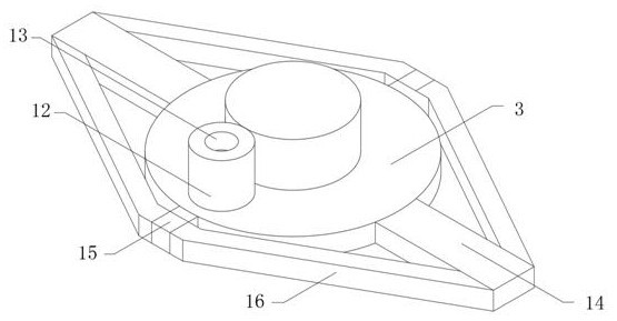
[0023]Example 3 is based on Example 2 asimage 3 As shown, the top end of the support base 3 is fixedly provided with a fixed post 12, and the top end of the fixed post 12 is provided with a fixed groove 13.


PUM


Abstract

The invention discloses an industrial display screen connecting wire winding mechanism which comprises a display screen body, a fixing block is fixedly arranged on one side of the display screen body,a first rotating disc is rotatably arranged on one side of the fixing block, a second rotating disc is rotatably arranged on one side of the first rotating disc through a rotating shaft, and a connecting rod is hinged to one side of the outer wall of the first rotating disc. According to the connecting wire winding mechanism of the industrial display screen, through fixing of the second rotary disc, the connecting wire is fixed to the outer side of the rotary shaft, and the handle is rotated, so that redundant connecting wires are wound tightly; the connecting rod is clamped into the clampinggroove of the fixing ring on the outer wall of the second rotary disc to prevent the connecting line from falling off, the connecting line of the display screen is stably placed, the end of the connecting line is stably connected with the display screen body, falling off is avoided, and files are prevented from being lost.

Description

Technical field[0001]The invention relates to a connecting wire winding mechanism of an industrial display screen, in particular to a connecting wire winding mechanism of an industrial display screen, belonging to the technical field of winding mechanisms.Background technique[0002]Industrial liquid crystal displays are liquid crystal displays used in industry, with a variety of display sizes and installation methods. Different from ordinary liquid crystal displays, it can adapt to extreme environments, run stably, and have a long service life.[0003]In response to this, Chinese Patent No. CN210836045U proposes an industrial display screen, which is completely embedded and installed on the top step of the front case through the touch screen, and its height is flush with the height of the side wall of the front case 1, making the industrial display screen compact. Disassembly and installation are very convenient. Chinese Patent No. CN210253497U proposes a dustproof device on industrial...

Claims


Application Information

Patent Timeline
Patent Type & Authority Applications(China)
IPC IPC(8): G06F1/16
CPCG06F1/1601
Inventor 谭轩
Owner 西安德创自动化工程有限公司
Why Eureka
Try Eureka