Turnover adjusting device for electromechanical machining

An adjustment device, electromechanical technology, applied in the direction of auxiliary devices, metal processing, metal processing equipment, etc., can solve the problems of inability to achieve integration, increase manufacturing costs, and reduce practicability, and achieve simple structure, reduce manufacturing costs, and improve stability sexual effect

Inactive Publication Date: 2021-01-12
WENZHOU UNIVERSITY
View PDF4 Cites 2 Cited by
  • Summary
  • Abstract
  • Description
  • Claims
  • Application Information

AI Technical Summary

Problems solved by technology

[0004] The purpose of the present invention is to solve the problems in the prior art that clamping and flipping need to be realized by two independent mechanisms, which cannot be integrated, thereby increasing the manufacturing cost and reducing the practicality, resulting in complex structure and inconvenient operation. disadvantages, while a proposed flip adjustment device for electromechanical machining

Method used


Image

  • Turnover adjusting device for electromechanical machining
  • Turnover adjusting device for electromechanical machining
  • Turnover adjusting device for electromechanical machining

Examples


Embodiment 1

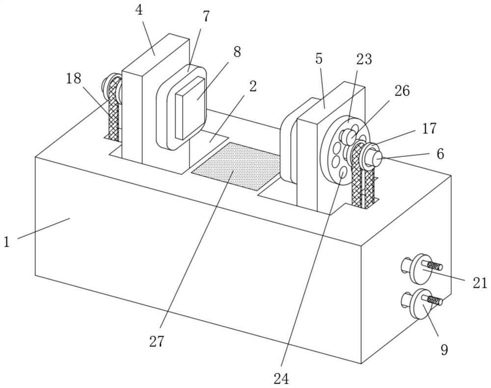
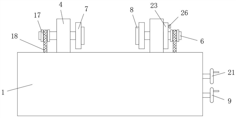
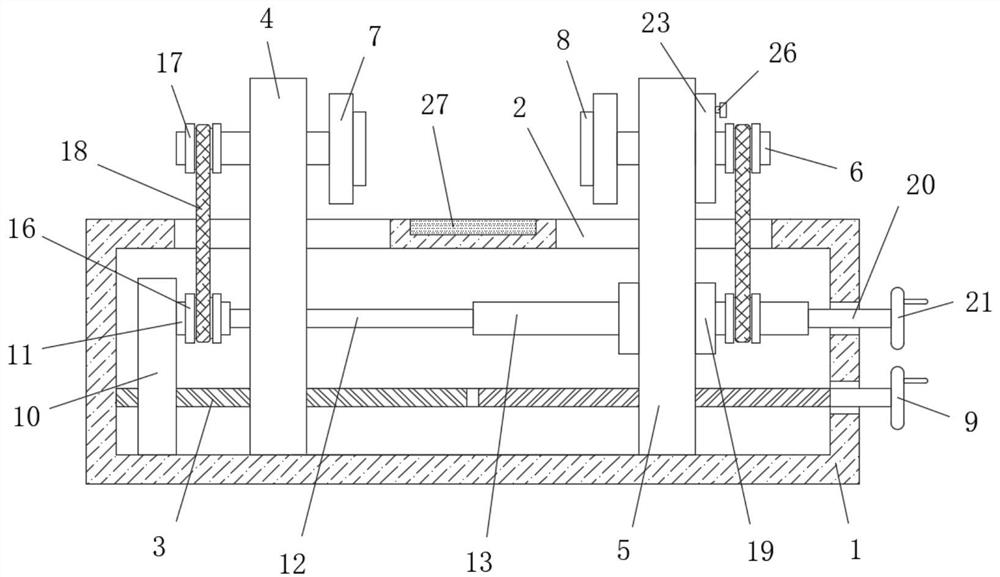
[0030] refer to Figure 1-7 , a flip adjustment device for electromechanical processing, including a base 1, and the base 1 is a hollow structure, two moving holes 2 are symmetrically opened on the top of the base 1, and the two moving holes 2 are connected with the inside of the base 1, and the base The internal rotation of 1 is connected with a screw rod 3, and the screw rod 3 is respectively threaded with a first nut plate 4 and a second nut plate 5, and the first nut plate 4 and the second nut plate 5 are arranged symmetrically, and the first nut plate 4 and the bottom of the second nut plate 5 are respectively slidingly connected with the bottom inner wall of the base 1, and one side of the first nut plate 4 and the second nut plate 5 respectively pass through two moving holes 2 and both extend to the top of the base 1. The top of one side of the nut plate 4 and the second nut plate 5 that are close to each other is connected with a first rotating rod 6 for rotation, and ...

Embodiment 2

[0032] Further improvement on the basis of Embodiment 1: The screw rod 3 is symmetrically provided with two sections of reverse threads, and the first nut plate 4 and the second nut plate 5 are respectively located on the two sections of reverse threads. When the screw rod 3 rotates, The first nut plate 4 and the second nut plate 5 can be moved relative to each other through two sections of reverse threads, and the end of the screw rod 3 close to the second nut plate 5 runs through one side of the base 1 and is fixedly connected with the first turntable 9, the third The end of the rotating rod 20 away from the rotating cylinder 13 runs through the side of the base 1 and is fixedly connected with the second turntable 21, and the side of the first turntable 9 and the second turntable 21 far away from the base 1 is fixedly connected with a rocker. The first rotating disk 9 and the second rotating disk 21 can drive the screw rod 3 and the third rotating rod 20 to rotate respectivel...


PUM


Abstract

The invention belongs to the technical field of electromechanical machining devices, particularly relates to a turnover adjusting device for electromechanical machining. The turnover adjusting deviceaims at solving the problems that in the prior art, clamping and turnover need to be achieved through two independent mechanisms, integration cannot be achieved, and therefore the manufacturing cost is improved, the practicability is reduced, a structure is complex, and operation is inconvenient. According to the solution, the turnover adjusting device comprises a base, the base is of a hollow structure, two moving holes are symmetrically formed in the top of the base and communicate with the interior of the base, and two rotating plates can be driven to relatively move by rotating a first rotating plate, so that the fixing and clamping effect on a workpiece is achieved, meanwhile, a second rotating rod and a rotating cylinder can be driven to move relatively, driving of a belt cannot be affected, the workpiece turning over effect can be achieved by rotating a second rotating plate at the moment, the whole structure is simple, operation is convenient, practicability is high, and the manufacturing cost is reduced.

Description

technical field [0001] The invention relates to the technical field of electromechanical processing devices, in particular to a flip adjustment device for electromechanical processing. Background technique [0002] Mechanical and electrical equipment generally refers to machinery, electrical appliances and electrical automation equipment. With the continuous improvement of technology, traditional mechanical equipment has entered a new stage of combination of machinery and electricity, and its application range has been continuously expanded. Since the 1960s, computers have gradually The popularization of industrial scientific research, design, production and management has created conditions for the development of the machinery manufacturing industry in a more complex and precise direction. Electromechanical equipment has also begun to develop towards digitization, automation, intelligence and flexibility, and has entered the new era of modern equipment. There are many types...

Claims


Application Information

Patent Timeline
Patent Type & Authority Applications(China)
IPC IPC(8): B23Q7/00B23K37/047B25H1/10
CPCB23K37/047B23Q7/00B25H1/10
Inventor 何小虹周斯加
Owner WENZHOU UNIVERSITY
Why Eureka
Try Eureka