
Wheel hub motor of rail chassis vehicle

A hub motor and chassis technology, which is applied to the transmission device, electromechanical device, and electrical components driven by an electric motor, can solve the problems of hub motor burnout, heat increase, and hub motor load increase

Active Publication Date: 2021-01-12
SHANGHAI ADVANCED POWER TECH
View PDF17 Cites 0 Cited by
  • Summary
  • Abstract
  • Description
  • Claims
  • Application Information

AI Technical Summary

Problems solved by technology

Although this can meet the needs of running vehicles under normal working conditions, when the vehicle encounters special working conditions, such as climbing, snow, and muddy road conditions, obviously the load on the hub motor will increase, and the heat will increase sharply during the working process. , the existing air-cooled heat dissipation system is difficult to meet the above heat dissipation requirements, which may lead to the occurrence of burnout of the hub motor; therefore, it is necessary for those skilled in the art to improve this

Method used


Image

  • Wheel hub motor of rail chassis vehicle
  • Wheel hub motor of rail chassis vehicle
  • Wheel hub motor of rail chassis vehicle

Examples


Embodiment 1

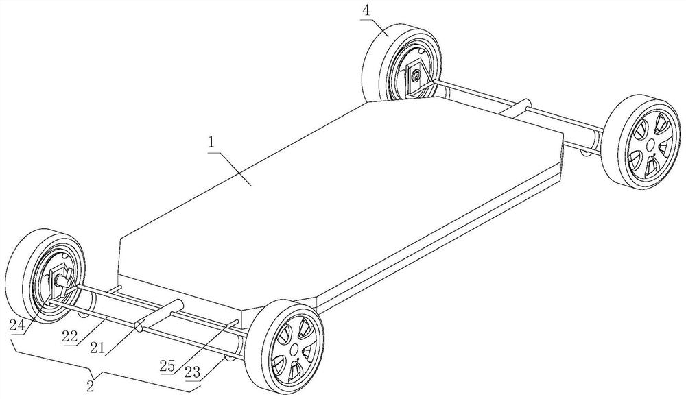
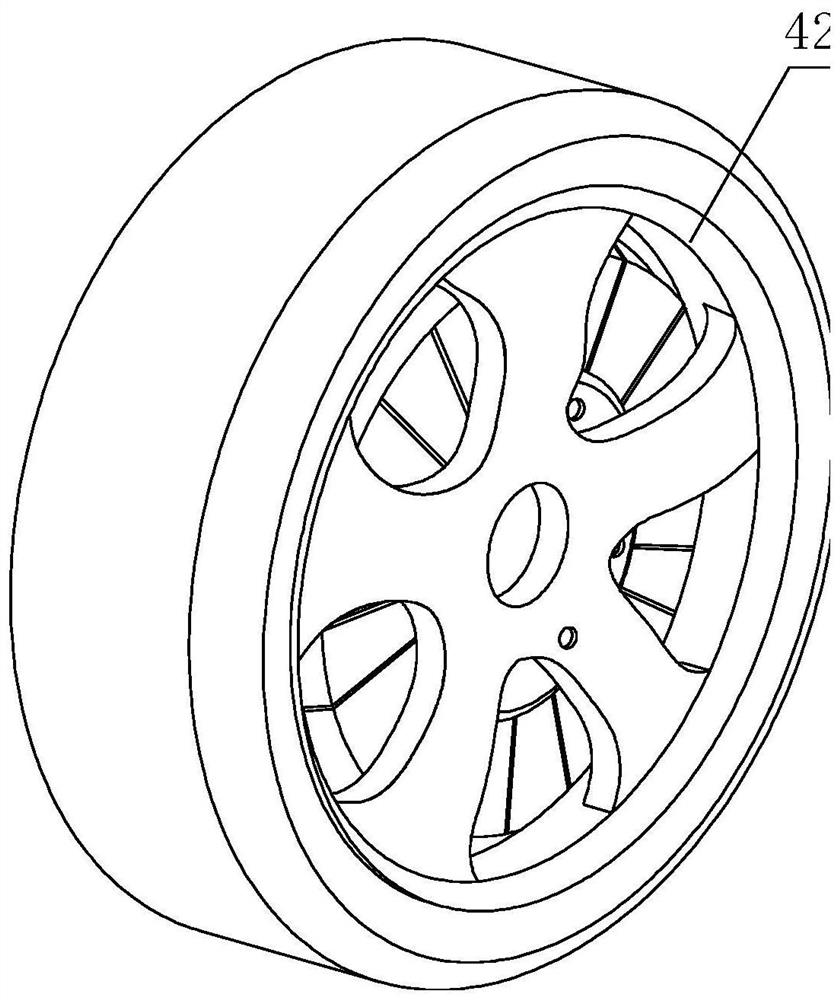
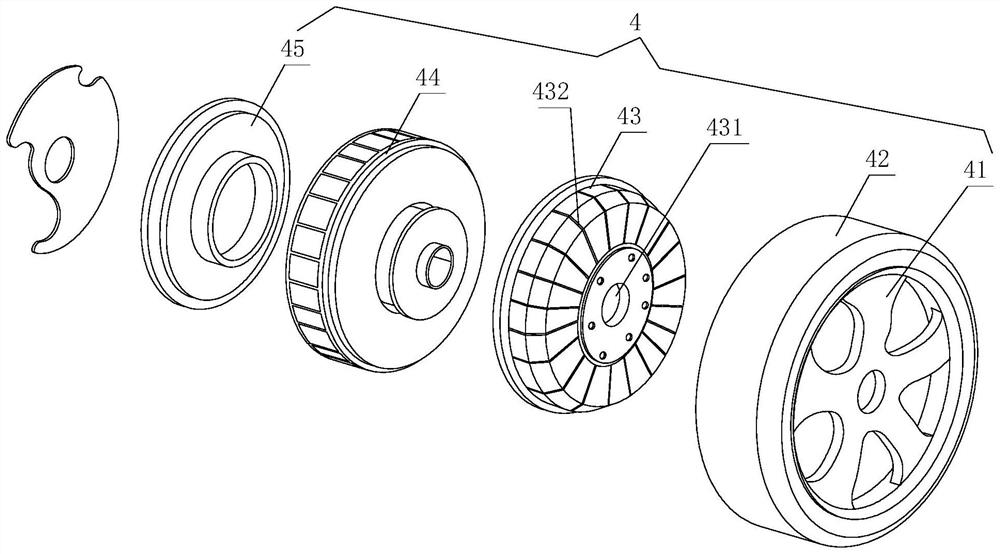
[0032] see figure 1 , a rail chassis wheel hub motor, including a chassis 1 and a vehicle frame 2, the vehicle frame 2 is installed on the front and rear sides of the chassis 1, and the vehicle frame 2 serves as a buffer and support function, and its softness and hardness are adjusted according to the use of the rail chassis vehicle The rigidity makes it more comfortable for the matching device, and the frame 2 also has a certain shock absorption function. The increased shock absorption allows the rail chassis vehicle to have a higher balance effect during operation, and on the frame 2 Connect the suspension 3 for the fixed hub motor, the function of the suspension 3 is to transfer the force and torque between the hub motor assembly 4 and the frame 2, and use the buffer to transmit the uneven road surface to the frame 2 or The impact force of the chassis 1 and reduce the vibration caused by it, the suspension 3 is connected with the hub motor assembly 4 and the cooling device ...

Embodiment 2

[0043] Change the structure of the cooling device 5, and the remaining parts are the same as the first embodiment. The cooling device 5 includes a sleeve 51, a shaft rod 52, a liquid inlet pipe 53 and a liquid outlet pipe 54, and the liquid inlet pipe 53 and the liquid outlet pipe 54 are symmetrically arranged on the On both sides of the sleeve 51, the liquid inlet pipe 53 and the liquid outlet pipe 54 are located in the radial direction of both sides, and the nozzle diameters of the two are the same. The liquid inlet pipe 53 is connected with the output end of the cooling assembly, and the liquid outlet pipe 54 is connected to the input end of the refrigeration assembly. When the refrigeration assembly is working, the temperature of the cooling liquid is lowered and flows into the liquid inlet pipe 53. What flows in the liquid outlet pipe 54 is the cooling liquid that has exchanged heat and flows into the refrigeration assembly for re-refrigeration. The continuous circulation ...

Embodiment 3

[0046] Change the structure of the cooling device 5, and the remaining parts are the same as in Embodiment 1. The cooling device 5 includes a shaft rod 52, a liquid inlet pipe 53 and a liquid outlet pipe 54, and the liquid inlet pipe 53 and the liquid outlet pipe 54 are arranged symmetrically on the sides of the shaft rod 52 respectively. On both sides, and both nozzle diameters are the same, the liquid inlet pipe 53 is connected to the output end of the refrigeration assembly, and the liquid outlet pipe 54 is connected to the input end of the refrigeration assembly, and the temperature of the cooling liquid is reduced when the refrigeration assembly is working. In the liquid pipe 53 and the liquid outlet pipe 54, the cooling liquid that has exchanged heat flows into the refrigeration assembly, and re-refrigerates to complete the continuous circulation of the cooling liquid, thereby realizing the function of continuously cooling the interior of the hub motor assembly 4 , the li...


PUM

PropertyMeasurementUnit
Lengthaaaaaaaaaa

Abstract

The invention discloses a wheel hub motor of a rail chassis vehicle, which belongs to the technical field of wheel hub motors and comprises a chassis and a vehicle frame, the vehicle frame is arrangedon the front side and the rear side of the chassis and is connected with a suspension for fixing the wheel hub motor, and the suspension is connected with a wheel hub motor assembly and a cooling device, and the cooling device extends to the hub motor assembly to reduce the temperature. According to the wheel hub motor of the rail chassis vehicle, cooling liquid is discharged into the shaft rod through the liquid inlet pipe and the liquid outlet pipe to achieve internal cooling of the shaft rod, the liquid inlet pipe and the liquid outlet pipe are symmetrically arranged on the two side facesof the sleeve base respectively and located in the same radial direction, and the liquid outlet pipe is connected with the input end of the refrigeration assembly; when the refrigeration assembly works, the temperature of the cooling liquid is reduced, the cooling liquid flows into the liquid inlet pipe, the cooling liquid subjected to heat exchange flows into the liquid outlet pipe and flows intothe refrigeration assembly, refrigeration is conducted again, and therefore continuous circulation of the cooling liquid is completed, and the function of continuously dissipating heat in the hub motor assembly is achieved.

Description

technical field [0001] The invention relates to the technical field of wheel hub motors, in particular to a wheel hub motor of a track chassis. Background technique [0002] In order to reduce energy consumption and reduce environmental pollution, electric vehicles with zero pollution and zero emissions have attracted more and more attention with clean energy as the power. In-wheel motor driven electric vehicle has become a research hotspot because of its simple mechanical transmission structure, high driving efficiency, low cost and many other advantages. The driving mode of the existing electric vehicle is to adopt a central motor plus a mechanical transmission mode mechanical differential or a hub motor plus an electronic software differential. [0003] Although the mechanical differential can achieve a perfect differential speed, it can ensure that the left and right hub motors rotate at different speeds, so that the hub motors on both sides can drive at unequal distanc...

Claims


Application Information

Patent Timeline
IPC IPC(8): B61C9/46H02K9/19H02K7/00H02K11/30
CPCB61C9/46H02K9/19H02K7/006H02K11/30
Inventor 秦小雷
Owner SHANGHAI ADVANCED POWER TECH
Learn More