Adjusting device for sound outlet angle of loudspeaker and implementation method thereof

A technology for adjusting a device and a loudspeaker, applied in the field of loudspeakers, can solve the problems of long consumption time, difficulty in adjusting the sound output angle of the loudspeaker, and great influence on the performance of the loudspeaker.

Inactive Publication Date: 2021-01-12
安徽井利电子有限公司
View PDF0 Cites 1 Cited by
  • Summary
  • Abstract
  • Description
  • Claims
  • Application Information

AI Technical Summary

Problems solved by technology

[0002] The loudspeaker, also known as the horn, is a very commonly used electro-acoustic transducer device. It is a transducer device that converts electrical signals into acoustic signals. The performance of the speaker has a great impact on the sound quality. It is the weakest device, and it is the most important part for the sound effect. There are many kinds of speakers, and the prices vary greatly. There are many types of speakers, which can be divided into electric, electrostatic, electromagnetic, piezoelectric, etc. , the latter two are mostly used in rural cable broadcasting networks, and can be divided into low-frequency speakers, intermediate-frequency speakers, and high-frequency speakers according to the frequency range. Adjust the sound angle of the speaker to achieve the most perfect sound quality, and the current speaker installation components do not contain components for separately adjusting the sound angle of the speaker, and the method of adjusting the sound angle is by adjusting the speaker Changing the overall installation position and angle will take a long time and the process will be more complicated. At the same time, it is difficult to adjust the speaker to the best sound angle.

Method used


Image

  • Adjusting device for sound outlet angle of loudspeaker and implementation method thereof
  • Adjusting device for sound outlet angle of loudspeaker and implementation method thereof
  • Adjusting device for sound outlet angle of loudspeaker and implementation method thereof

Examples


Embodiment 1

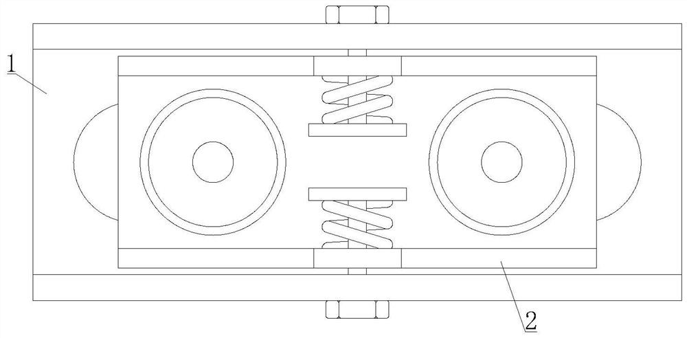
[0030] see Figure 1-Figure 2 A device for adjusting the sound output angle of a loudspeaker comprises a loudspeaker shell 1 and an embedded speaker 2, and the built-in loudspeaker 2 is installed inside the loudspeaker shell 1.

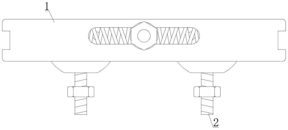
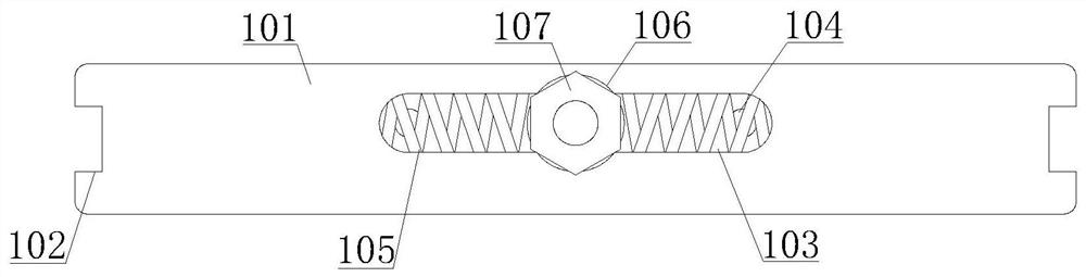
[0031] see Figure 3-Figure 4 , the loudspeaker housing 1 includes a main housing 101, a mounting card socket 102, a side slide groove 103, a fixing screw hole 104, a return spring 105, an embedded slider 106, a locking bolt 107, an inner mounting groove 108, a bottom opening 109 and a spring Plate 1010, the two ends of the main casing 101 are respectively provided with mounting card sockets 102, the front and rear sides of the main casing 101 are respectively provided with side chute 103, the bottom of the side chute 103 is provided with fixing screw holes 104, and the side chute Back-moving springs 105 are respectively installed at the inner two ends of 103, and embedded slide block 106 is installed in the side chute 103 between back-moving springs...

Embodiment approach

[0034] In order to better demonstrate the implementation process of the device for adjusting the sound output angle of the speaker, this embodiment now proposes an implementation method for the device for adjusting the sound output angle of the speaker, including the following steps:

[0035] Step 1: install and adjust the speaker panel 255 in the speaker assembly 25, and insert the speaker assembly 25 into the inner card slot 24 in the outer frame 21;

[0036] Step 2: Nest the built-in speaker 2 in the speaker housing 1 as a whole, pass the locking bolt 107 through the center of the adjusting screw hole 23 and the adjusting spring 26, and install the spring plate 1010 at the end of the locking bolt 107;

[0037] Step 3: According to the required sound output angle, operate the locking bolt 107 to adjust the inclination angle of the outer frame 21 so that the outer frame 21 and the speaker shell 1 present a certain angle;

[0038] Step 4: Adjust the position of the built-in sl...

Embodiment 2

[0040] see Figure 1-Figure 2 A device for adjusting the sound output angle of a speaker includes a speaker shell 1 and an embedded speaker 2, and the speaker shell 1 is installed with the embedded speaker 2.

[0041] see Figure 3-Figure 4 , the loudspeaker housing 1 includes a main housing 101, a mounting card socket 102, a side slide groove 103, a fixing screw hole 104, a return spring 105, an embedded slider 106, a locking bolt 107, an inner mounting groove 108, a bottom opening 109 and a spring Plate 1010, the two ends of the main casing 101 are respectively provided with mounting card sockets 102, the front and rear sides of the main casing 101 are respectively provided with side chute 103, the bottom of the side chute 103 is provided with fixing screw holes 104, and the side chute Back-moving springs 105 are respectively installed at the inner two ends of 103, and embedded slide block 106 is installed in the side chute 103 between back-moving springs 105, and locking b...


PUM


Abstract

The invention discloses a loudspeaker sound outlet angle adjusting device and an implementation method thereof. The device comprises a loudspeaker shell and an embedded loudspeaker, wherein the embedded loudspeaker is installed in the loudspeaker shell through a locking bolt, and the inclination angle of an inner side outer frame is adjusted by rotating the locking bolt, so the rough adjustment ofthe sound outlet angle of the loudspeaker is completed; moreover, two different loudspeaker assemblies are arranged in the equipment, the loudspeaker panel in the first loudspeaker assembly cannot beadjusted, the loudspeaker panel completes adjustment of the sound outlet angle according to the inclination angle of the outer frame, the second loudspeaker assembly comprises a spherical adjusting rod, so the spherical adjusting rod rotates under the action of the sliding ball, so the loudspeaker panel inclines to a certain degree, rough adjustment and fine adjustment of the sound outlet angle are achieved, the time consumed for adjusting the installation direction of the loudspeaker is saved, the time consumed for adjustment is short, the process is simple, the practicability is high, and the loudspeaker can be rapidly adjusted to the optimal sound outlet angle.

Description

technical field [0001] The invention relates to the technical field of loudspeakers, in particular to a device for adjusting the sound output angle of a loudspeaker and an implementation method thereof. Background technique [0002] The loudspeaker, also known as the horn, is a very commonly used electro-acoustic transducer device. It is a transducer device that converts electrical signals into acoustic signals. The performance of the speaker has a great impact on the sound quality. It is the weakest device, and it is the most important part for the sound effect. There are many kinds of speakers, and the prices vary greatly. There are many types of speakers, which can be divided into electric, electrostatic, electromagnetic, piezoelectric, etc. , the latter two are mostly used in rural cable broadcasting networks, and can be divided into low-frequency speakers, intermediate-frequency speakers, and high-frequency speakers according to the frequency range. Adjust the sound a...

Claims


Application Information

Patent Timeline
IPC IPC(8): H04R1/02H04R1/32
CPCH04R1/026H04R1/323
Inventor 张建栋
Owner 安徽井利电子有限公司
Why Eureka
Try Eureka