Micro speaker based on mems ultrasonic transducer
A micro-speaker and ultrasonic technology, applied in the field of microelectronics, can solve the problems of low sound pressure sensitivity and low energy conversion efficiency of the speaker, and achieve the effects of high energy conversion efficiency, small envelope distortion, and high sound pressure sensitivity
- Summary
- Abstract
- Description
- Claims
- Application Information
AI Technical Summary
Problems solved by technology
Method used
Image
Examples
Embodiment 1
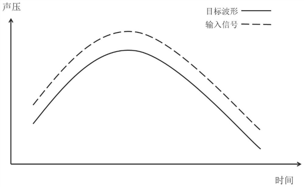
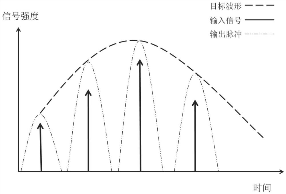
[0045] like Figure 8a and Figure 8b shown, where Figure 8b The control circuit part in is omitted and not drawn. Figure 8b Among them, 001 denotes the substrate, and 002 denotes the MEMS ultrasonic transducer. The MEMS ultrasonic transducer 002 is controlled by discrete or approximately discrete electrical signals sent by the control circuit, and emits multiple ultrasonic pulses or wave envelope sound waves. These sound waves are superimposed in the time domain to form a synthetic sound wave envelope, approximating the target audio sound wave. The center frequency or resonant frequency of the MEMS ultrasonic transducer 002 is greater than 20 kHz. The FWHM of the pulse time domain is less than 20μs. The MEMS ultrasonic transducer 002 may be of a piezoelectric type, a capacitive type, an electromagnetic type, or the like. The material of the substrate 001 can be silicon, quartz, lithium niobate, lithium tantalate, gallium arsenide and the like. The MEMS ultrasonic tran...
Embodiment 2
[0047] like Figure 9a and Figure 9b shown, where Figure 9b The control circuit part in is omitted and not drawn. Figure 9b Among them, 001 denotes the substrate, and 002 denotes the MEMS ultrasonic transducer. A plurality of MEMS ultrasonic transducers 002 form an array, including but not limited to linear, 2-dimensional or 3-dimensional forms. Each MEMS ultrasonic transducer 002 acts as an element of the array. Each array element of the transducer array can be the same, which has the advantage of being easy to control and easy to manufacture; the array elements can also be different, for example, have different center frequencies, which can expand the bandwidth of the transducer array. The array element can be controlled digitally, that is, the amplitude is a fixed value when vibrating and sounding, and the size of the ultrasonic pulse signal can be adjusted by controlling the number of sounding array elements, thereby modulating the waveform of the audio sound wave; ...
Embodiment 3
[0049] like Figure 10a and Figure 10b shown, where Figure 10b The control circuit part in is omitted and not drawn. Figure 10b Among them, 001 represents the substrate, 002 represents the MEMS ultrasonic transducer, and 003 represents the impedance matching structure in the ultrasonic frequency band. The acoustic wave matching frequency band of the ultrasonic frequency band impedance matching structure 003 is in the ultrasonic frequency band. After adding the ultrasonic frequency band impedance matching structure 003 to the device, the output sound pressure of the sound wave is larger and the distortion is smaller. The impedance matching structure 003 in the ultrasonic frequency band may be a Helmholtz resonant cavity, a quarter-wavelength matching tube, an acoustic matching layer, etc., and the center frequency of the matching structure is in the ultrasonic frequency band.
PUM
 Abstract
Description
Claims
Application Information
 - R&D
- Intellectual Property
- Life Sciences
- Materials
- Tech Scout
- Unparalleled Data Quality
- Higher Quality Content
- 60% Fewer Hallucinations
Browse by: Latest US Patents, China's latest patents, Technical Efficacy Thesaurus, Application Domain, Technology Topic, Popular Technical Reports.
© 2025 PatSnap. All rights reserved.Legal|Privacy policy|Modern Slavery Act Transparency Statement|Sitemap|About US| Contact US: help@patsnap.com


