
Preparation method of fiber grating hydrophone for measuring near-field sound pressure distribution of high-frequency transducer

A technology of high-frequency transducers and optical fiber gratings, applied in the direction of measuring ultrasonic/sonic/infrasonic waves, instruments, measuring devices, etc., can solve the problems of poor precision, low efficiency, and low sound pressure sensitivity, and achieve small size and sound pressure High sensitivity and good spatial resolution

Inactive Publication Date: 2017-08-04
CHINA JILIANG UNIV
View PDF9 Cites 0 Cited by
  • Summary
  • Abstract
  • Description
  • Claims
  • Application Information

AI Technical Summary

Problems solved by technology

[0005] The purpose of the present invention is to provide a traditional piezoelectric ceramic or PVDF ultrasonic hydrophone with large size, low spatial resolution, strong scattering of high-frequency sound waves, and low sound pressure sensitivity of ordinary bare fiber grating hydrophones. A fiber grating hydrophone for measuring the near-field sound pressure distribution of a high-frequency transducer and a preparation method thereof. The fiber grating hydrophone has the advantages of compact structure, high spatial resolution, high sound pressure sensitivity, and can be arrayed. Solve a series of problems such as low efficiency, poor precision, and low sound pressure sensitivity in the sound field measurement of high-frequency transducers, and are suitable for near-field characteristic measurement of high-frequency sound fields

Method used


Image

  • Preparation method of fiber grating hydrophone for measuring near-field sound pressure distribution of high-frequency transducer

Examples


Embodiment Construction

[0021] The present invention will be described in detail below in conjunction with the accompanying drawings and embodiments.

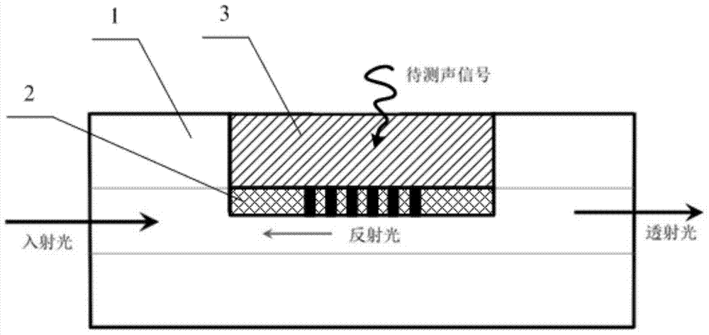
[0022] Such as figure 1 As shown, the fiber Bragg grating hydrophone for measuring the near-field sound pressure distribution of the high-frequency transducer is composed of a D-type standard single-mode fiber 1, a polymer ridge-shaped thin-film optical waveguide Bragg grating 2 and a polymer-coated filling layer 3; D-type standard single-mode fiber 1 is a silicon oxide standard single-mode fiber whose side is polished to form a coating groove; polymer ridge-shaped film optical waveguide Bragg grating 2 covers the bottom surface of the D-type standard single-mode fiber 1 filling groove; polymer coating The filling layer 3 covers the polymer ridge film optical waveguide Bragg grating 2 for encapsulation protection and further acoustic sensitization; the polymer ridge film optical waveguide Bragg grating 2 consists of a polymer ridge film optical wavegu...


PUM


Abstract

The invention discloses a fiber grating hydrophone for measuring near-field acoustic pressure distribution of a high-frequency transducer and a manufacturing method. Conventional piezoelectric ceramic or PVDF ultrasonic hydrophones are low in space resolution and high in high-frequency acoustic wave scattering. A polymer ridge-type thin film light waveguide bragg grating covers the undersurface of a full-filling groove of a D-type standard single-mode optical fiber, and a polymer coating filling layer covers the polymer ridge-type thin film light waveguide bragg grating. The manufacturing method includes: polishing the side face of the standard single-mode optical fiber to form the full-filling groove, and covering polymer ridge-type thin film light waveguide at the bottom of the full-filling groove; making a grating groove in the polymer ridge-type thin film light waveguide to form the polymer ridge-type thin film light waveguide bragg grating; covering second polymer on the polymer ridge-type thin film light waveguide bragg grating. By the fiber grating hydrophone, the problem that the high-frequency transducer is low in acoustic field measuring efficiency, poor in accuracy and low in acoustic pressure sensitivity can be solved; the fiber grating hydrophone is suitable for near-field characteristic measuring of high-frequency acoustic fields.

Description

technical field [0001] The invention belongs to the field of high-frequency ultrasonic field measurement, and in particular relates to a preparation method of a fiber grating hydrophone used for measuring the near-field sound pressure distribution of a high-frequency transducer. Background technique [0002] With the widespread use of medical ultrasound, high-frequency transducers are used more and more widely, and the measurement of their sound field characteristics, especially the near-field sound pressure distribution, is attracting people's attention. The sound field characteristics of high-frequency transducers are usually detected by hydrophones, and the near-field sound pressure distribution is acquired by spatial scanning of hydrophones to obtain acoustic signals (amplitude, phase) at different positions and then obtained by data processing. Considering the need to reduce the disturbance of the hydrophone to the sound field to be measured as much as possible during n...

Claims


Application Information

Patent Timeline
Patent Type & Authority Patents(China)
IPC IPC(8): G01H9/00
Inventor 王月兵李威郑慧峰唐廷浩王成
Owner CHINA JILIANG UNIV
Learn More