Eureka AIR delivers breakthrough ideas for toughest innovation challenges, trusted by R&D personnel around the world.

Efficient automatic conveying turnover mechanism for workpiece machining

A turning mechanism and automatic conveying technology, which is applied in the direction of conveyor objects, transportation and packaging, etc., can solve the problems of reducing the efficiency of workpiece conveying, reducing the adaptability of the device, and being unable to adjust the distance and height of workpieces, so as to achieve the effect of improving efficiency

Inactive Publication Date: 2021-01-15
胡明良
View PDF6 Cites 1 Cited by
  • Summary
  • Abstract
  • Description
  • Claims
  • Application Information

AI Technical Summary

Problems solved by technology

[0003] However, the existing workpiece conveying and turning mechanism requires manual or other control mechanisms to perform secondary operations when conveying the workpiece to the node that needs to be turned over, which increases the complexity of the operation and reduces the need for the workpiece. At the same time, most of the existing conveying mechanisms are fixed structures, and the distance and height of workpiece conveying cannot be adjusted according to the demand, which reduces the adaptability of the device. Therefore, an efficient automatic conveying and turning mechanism for workpiece processing is urgently needed to solve the above-mentioned problems

Method used


Image

  • Efficient automatic conveying turnover mechanism for workpiece machining
  • Efficient automatic conveying turnover mechanism for workpiece machining
  • Efficient automatic conveying turnover mechanism for workpiece machining

Examples


Embodiment Construction

[0030] The following will clearly and completely describe the technical solutions in the embodiments of the present invention with reference to the accompanying drawings in the embodiments of the present invention. Obviously, the described embodiments are only some, not all, embodiments of the present invention. Based on the embodiments of the present invention, all other embodiments obtained by persons of ordinary skill in the art without making creative efforts belong to the protection scope of the present invention.

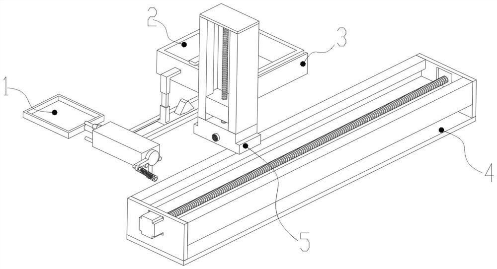
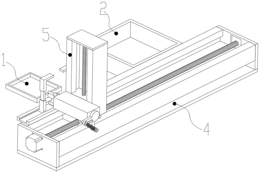
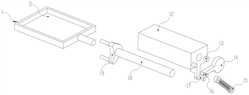
[0031] see Figure 1-10 , an embodiment provided by the present invention: a high-efficiency automatic conveying and turning mechanism for workpiece processing, including a turning mechanism 1, a positioning frame 2, a supporting clamp 3, a supporting mechanism 4 and an adjusting mechanism 5,

[0032] The upper end surface of the support mechanism 4 is threaded and slidably connected with the adjustment mechanism 5 for support, and the front end surface of the...


PUM


Abstract

The invention discloses an efficient automatic conveying turnover mechanism for workpiece machining. The efficient automatic conveying turnover mechanism comprises a turnover mechanism, a positioningframe, a supporting clamping plate, a supporting mechanism and an adjusting mechanism; and the upper end face of the supporting mechanism is in threaded sliding connection with the adjusting mechanismused for supporting. By arranging the adjusting mechanism, when a turnover base reaches the limit position, a connecting motor can drive the adjusting mechanism to return and meanwhile drive the turnover mechanism to descend, and due to the fact that fixing rods are limited and turned over in front of adjusting plates, at the moment, the two sets of fixing rods of a guide head face inwards and just pass through the space between the two sets of adjusting plates during falling; and meanwhile, when the fixing rods fall to make contact with a guide clamping block, the fixing rods can be attachedto the other side edge of the guide clamping block to move downwards, so that a connecting sliding block moves towards one side, the bent positions of the upper parts of the adjusting plates block the upper parts of the fixing rods on the other side again, subsequent secondary turnover and conveying are facilitated, and the circulating conveying efficiency of the device is effectively improved.

Description

technical field [0001] The invention relates to the technical field of mechanical equipment, in particular to an automatic conveying and turning mechanism for workpiece processing with high efficiency. Background technique [0002] Most of the existing mechanical processing equipment are processed in batches when processing workpieces, which can effectively improve the efficiency of workpiece production. The workpiece conveying and turning mechanism can uniformly convey and unload batches of workpieces, thereby facilitating Follow-up to improve the efficiency of collecting and managing artifacts. [0003] However, the existing workpiece conveying and turning mechanism requires manual or other control mechanisms to perform secondary operations when conveying the workpiece to the node that needs to be turned over, which increases the complexity of the operation and reduces the need for the workpiece. At the same time, most of the existing conveying mechanisms are fixed struct...

Claims


Application Information

Patent Timeline
Patent Type & Authority Applications(China)
IPC IPC(8): B65G47/248B65G47/74
CPCB65G47/248B65G47/74
Inventor 胡明良
Owner 胡明良
Why Eureka
Eureka Blog
Learn More