Remote control machine room monitoring equipment based on TCP protocol

A technology of remote control and monitoring equipment, which is applied to the control mechanism of the wing leaf, the power control mechanism, the lock of the non-mechanical transmission control, etc., which can solve the problems of the anti-theft door in the computer room, such as poor resistance to violent break-in and automatic ventilation, etc. The door is firm and the effect of increasing safety

Active Publication Date: 2021-01-15
北京信智睿通信息技术有限责任公司
View PDF5 Cites 0 Cited by
  • Summary
  • Abstract
  • Description
  • Claims
  • Application Information

AI Technical Summary

Problems solved by technology

[0003] The technical problem to be solved by the present invention is to provide a remote control computer room monitoring device based on the TCP protocol, which solves the problem that the anti-theft door of the computer room is poor in resisting violent break-ins and cannot automatically ventilate the humidity of the computer room

Method used


Image

  • Remote control machine room monitoring equipment based on TCP protocol
  • Remote control machine room monitoring equipment based on TCP protocol
  • Remote control machine room monitoring equipment based on TCP protocol

Examples


Embodiment Construction

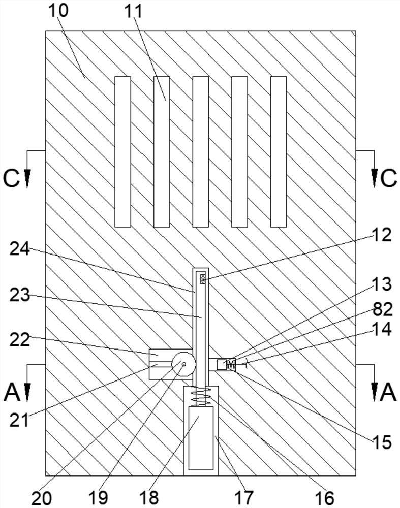
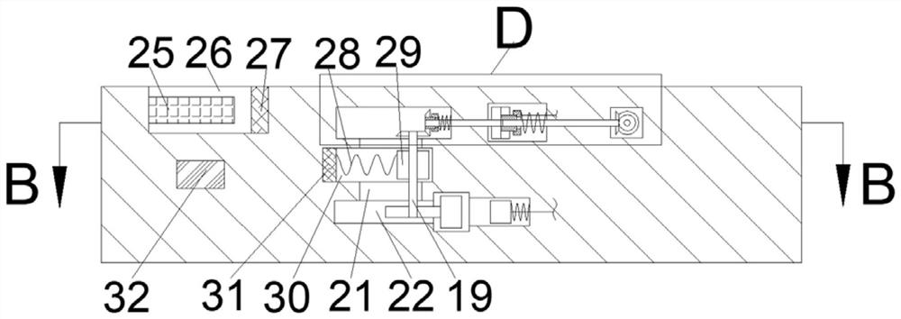
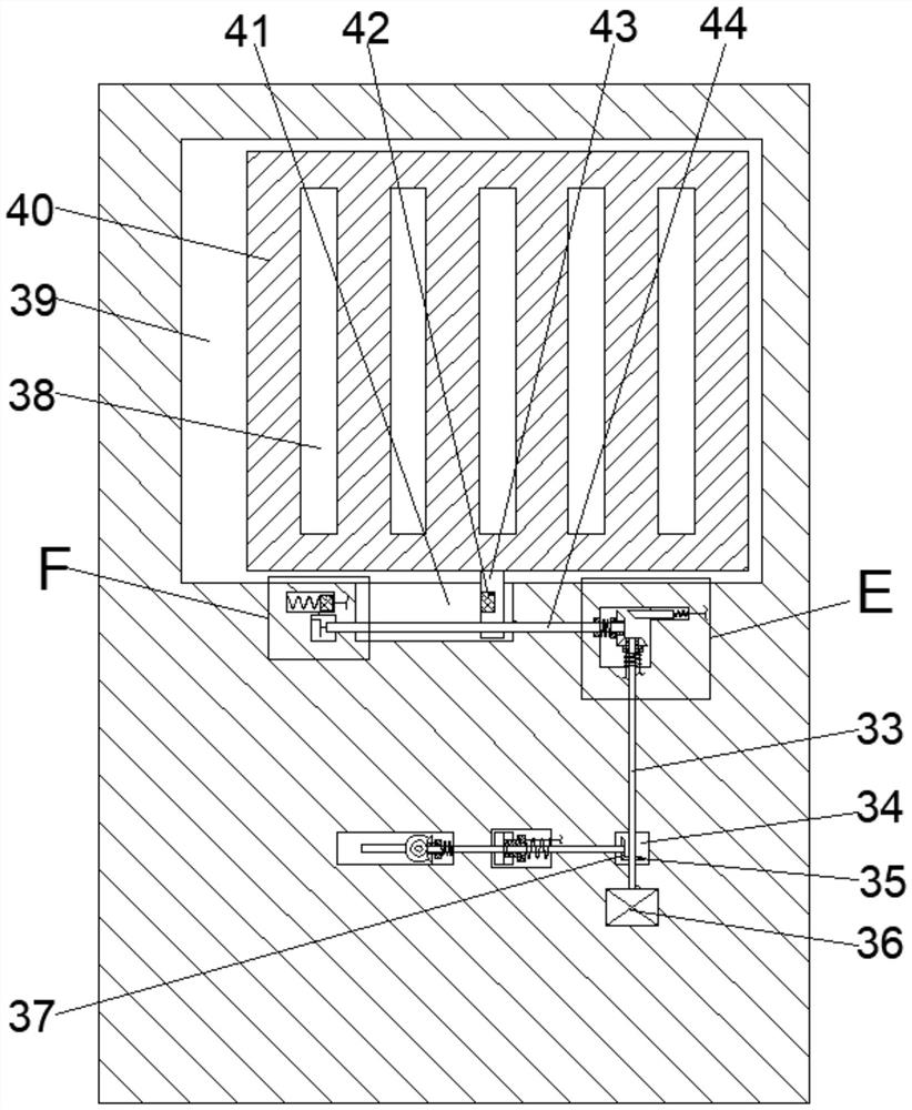
[0019] Combine below Figure 1-7 The present invention is described in detail, wherein, for the convenience of description, the orientations mentioned below are defined as follows: figure 1 The up, down, left, right, front and back directions of the projection relationship itself are the same.

[0020] combined with Figure 1-7 The described remote control computer room monitoring equipment based on the TCP protocol comprises a main box body 10, five equidistantly distributed ventilation cavities 11 are arranged in the said main box body 10, and teeth are arranged under the ventilation cavities 11. Rack chamber 24, the lower side of the rack chamber 24 is connected with a pin block chamber 17 with an opening downward, the left side of the rack chamber 24 is connected with a gear chamber 22, and the right side of the rack chamber 24 is connected with a The slider chamber 15, the rack chamber 24 is slidingly fitted with a rack 23 extending downwards into the pin block chamber ...


PUM


Abstract

The invention discloses a remote control machine room monitoring equipment based on TCP protocol. The remote control machine room monitoring equipment based on the TCP protocol comprises a main box body; five ventilation cavities distributed in an equally spaced manner are formed in the main box body; rack cavities are formed in the lower sides of the ventilation cavities; pin block cavities withdownward openings are formed in the lower sides of the rack cavities in a communicating mode; gear cavities are formed in the left sides of the rack cavities in a communicating mode; sliding block cavities are formed in the right sides of the rack cavities in a communicating mode; racks extending into the pin block cavities downwards are linked to the interiors of the rack cavities in a sliding fit mode; and rack magnets are fixedly linked to the interiors of the right end surfaces of the racks. When a machine room door is opened abnormally, such as violently, a pin block can be automaticallyinserted into a hole in the floor, so that a machine room door is firmer, the safety of the machine room is greatly improved, and the safety of the machine room is improved; and meanwhile, an operatorcan restore to an initial position through remote control, so that the machine room door can be reused; when the humidity in the machine room is too high, a ventilation opening can be automatically opened for ventilation, and meanwhile, the pin blocks are lowered, so that illegal personnel are prevented from illegally opening the machine room door through the ventilation opening.

Description

technical field [0001] The invention relates to the technical field of computer room monitoring, in particular to a remote control computer room monitoring device based on the TCP protocol. Background technique [0002] The computer room monitoring is mainly for the centralized monitoring and management of all the equipment and environment in the computer room, including environmental monitoring and security monitoring. In the link, the current security door of the computer room is generally an anti-theft door, but the general anti-theft door cannot resist violent break-ins, and cannot monitor the humidity in the computer room environment. If the humidity in the computer room is too high, the service life of the equipment in the computer room will be greatly reduced . Contents of the invention [0003] The technical problem to be solved by the present invention is to provide a remote control computer room monitoring device based on the TCP protocol, which solves the probl...

Claims


Application Information

Patent Timeline
Patent Type & Authority Applications(China)
IPC IPC(8): E06B5/11E05B47/00E05B15/10E05B15/00E06B7/04E05F15/632E05F15/70
CPCE05B15/00E05B15/101E05B47/0012E05B47/026E05B2047/002E05B2047/0028E06B5/11E06B7/04E05F15/632E05F15/70
Inventor 贾红岩
Owner 北京信智睿通信息技术有限责任公司
Why Eureka
Try Eureka