LED light source image detection method and device with stroboscopic suppression function

A LED light source and image detection technology, which is applied in image communication, energy-saving control technology, color TV components, etc., can solve problems such as the inability to detect LED lights from images, limited exposure, and overexposure of camera images, etc., to achieve Effects of avoiding motion blur effect, improving image detection performance, and suppressing stroboscopic effect

Active Publication Date: 2021-01-15
CHANGSHA XINGSHEN INTELLIGENT TECH CO LTD
View PDF6 Cites 0 Cited by
  • Summary
  • Abstract
  • Description
  • Claims
  • Application Information

AI Technical Summary

Problems solved by technology

[0003] Since the LED lamp is driven by AC, the flickering frequency of the LED is generally 100Hz (twice the mains frequency), that is, the pulse period is about 10 milliseconds, and the LED will be turned on and off once within 10 milliseconds, which is energy-saving and prolongs the use. Life, the duty cycle is usually set to no more than 50%, so when the camera captures the image of the LED light, if the camera exposure time is short (for example, 3 milliseconds), it is possible that the camera exposure time is just in the period when the LED is turned off , so that what the image sensor collects at this time is the image of the LED off. If the LED array is collected, in this case the image captured by the camera will show a part of the light and a part of the dark state, making it impossible to obtain from LED lights detected in the image
[0004] For example, electronic road signs, traffic signals, etc., and car tail lights usually use LED lights. At present, when detecting such LED lights such as electronic road signs, traffic signals, etc., car tail lights, etc., usually use ordinary cameras directly to capture pictures according to a fixed exposure time. , it is very easy to have the above-mentioned LED stroboscopic effect. The existence of the LED stroboscopic effect will cause the system to fail to detect electronic road signs and traffic lights, and cannot distinguish between turn signals and tail lights, etc., and even cause serious traffic accidents.
The photosensitive ability of the image sensor is certain, that is, its exposure is limited. If the above-mentioned stroboscopic effect problem is simply solved by dynamically increasing and adjusting the exposure time, if the exposure time is too long, there will be a problem of overexposure. To eliminate stroboscopic flicker, the exposure time of a conventional ordinary camera needs to be set at least greater than 7ms, and under this exposure time, some traffic lights will be brighter due to the large duty cycle of the LED bright cycle, and when working outdoors The superposition of ambient light, especially in the case of sufficient sunlight at noon, can easily lead to overexposure of the camera image, and long-term exposure can also cause problems such as motion blur effects

Method used


Image

  • LED light source image detection method and device with stroboscopic suppression function
  • LED light source image detection method and device with stroboscopic suppression function
  • LED light source image detection method and device with stroboscopic suppression function

Examples


Embodiment Construction

[0035] The present invention will be further described below in conjunction with the accompanying drawings and specific preferred embodiments, but the protection scope of the present invention is not limited thereby.

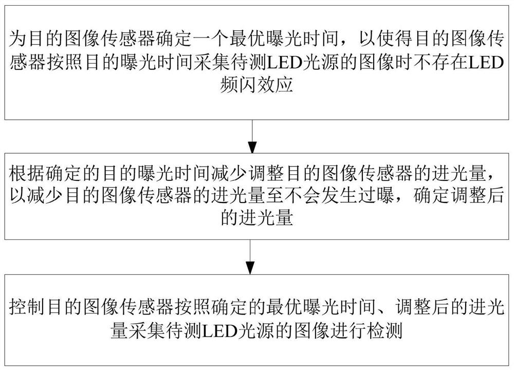
[0036] Such as figure 1As shown, the steps of the LED light source image detection method with stroboscopic suppression function in this embodiment include:

[0037] S1. Determine an optimal exposure time for the target image sensor, so that there is no LED stroboscopic effect when the target image sensor collects the image of the LED light source to be tested according to the target exposure time;

[0038] S2. According to the determined optimal exposure time, reduce and adjust the light input amount of the target image sensor, so as to reduce the light input amount of the target image sensor so that no overexposure occurs, and determine the adjusted light input amount;

[0039] S3. The control purpose image sensor collects the image of the LED light source to...


PUM


Abstract

The invention discloses an LED light source image detection method and device with a stroboscopic suppression function, and the method comprises the steps: S1, determining the optimal exposure time for a target image sensor, so as to enable the target image sensor not to have an LED stroboscopic effect when the target image sensor collects an image of a to-be-detected LED light source according tothe optimal exposure time; s2, reducing and adjusting the light incoming amount of the target image sensor according to the determined optimal exposure time so as to reduce the light incoming amountof the target image sensor until overexposure does not occur, and determining the adjusted light incoming amount; and S3, controlling a target image sensor to acquire an image of the LED light sourceto be detected for detection according to the optimal exposure time determined in the step S1 and the light incoming amount adjusted in the step S2. The LED stroboscopic effect can be suppressed whenthe LED light source is detected, and meanwhile, the overexposure phenomenon is avoided.

Description

technical field [0001] The invention relates to the technical field of LED light source detection, in particular to an image detection method and device for an LED light source with a flicker suppression function. Background technique [0002] As a diode device, LED can only pass through DC. When connected to the mains, it must use a power supply to convert the mains AC into DC, and the luminous brightness of the LED has a very short response time to the current, which will change with the current, that is, the LED The amount of current passed is proportional to the brightness of the light, and the amount of current passed will correspond to the amount of light emitted. Therefore, LED flickering is only related to the frequency and ripple of the output current of its driving power supply. The stroboscopic effect of LED light source is essentially that the light emitted by the light source will show a certain frequency and periodic change over time, and it will also change wi...

Claims


Application Information

Patent Timeline
Patent Type & Authority Applications(China)
IPC IPC(8): H04N5/235H04N5/353H04N5/355
CPCH04N23/741H04N23/73H04N25/53H04N25/57Y02B20/40
Inventor 孟德远胡庭波安向京
Owner CHANGSHA XINGSHEN INTELLIGENT TECH CO LTD
Why Eureka
Try Eureka