Big arm vibration measuring device for crane

A vibration measurement and crane technology, applied in the field of cranes, can solve the problems of the measurement object being detached, the fixation is not stable enough, the lifting is unsafe, etc., and the effect of improving stability and improving effect can be achieved.

Inactive Publication Date: 2021-01-22
徐强强
View PDF0 Cites 1 Cited by
  • Summary
  • Abstract
  • Description
  • Claims
  • Application Information

AI Technical Summary

Problems solved by technology

[0002] At present, during the operation of the crane, the boom of the crane will experience a certain degree of mechanical vibration, and when the frequency of the mechanical vibration exceeds the allowable vibration value, it will cause a large swing at the lifting end, making the lifting unsafe, and Long-term over-frequency vibration will lead to the gradual failure and damage of related parts, which will cause hidden dangers to the safety of the machine. Therefore, it is necessary to regularly use the relevant vibration measurement device to measure the vibration data of the running arm, but the general measurement device is in use. , its self-fixation is not stable enough, the connection with the measurement object is poor, and it is easy to cause relative vibration with the measurement object, which makes the measurement data inaccurate, and affected by the vibration of the measurement object, the measurement device is more likely to accidentally detach from the measurement object
[0003] Aiming at the deficiencies of the prior art, the present invention provides a boom vibration measuring device for a crane, which has the advantages of effectively improving the stability fixed to the measuring object, effectively improving the effect of vibration measurement, etc., and solving the problem of Solved the problem that the general boom vibration measurement device used for cranes is not stable enough to be fixed and easily detached from the measurement object during use, and the vibration measurement results are not accurate enough

Method used


Image

  • Big arm vibration measuring device for crane
  • Big arm vibration measuring device for crane
  • Big arm vibration measuring device for crane

Examples


Embodiment Construction

[0021] The following will clearly and completely describe the technical solutions in the embodiments of the present invention with reference to the accompanying drawings in the embodiments of the present invention. Obviously, the described embodiments are only some, not all, embodiments of the present invention. Based on the embodiments of the present invention, all other embodiments obtained by persons of ordinary skill in the art without making creative efforts belong to the protection scope of the present invention.

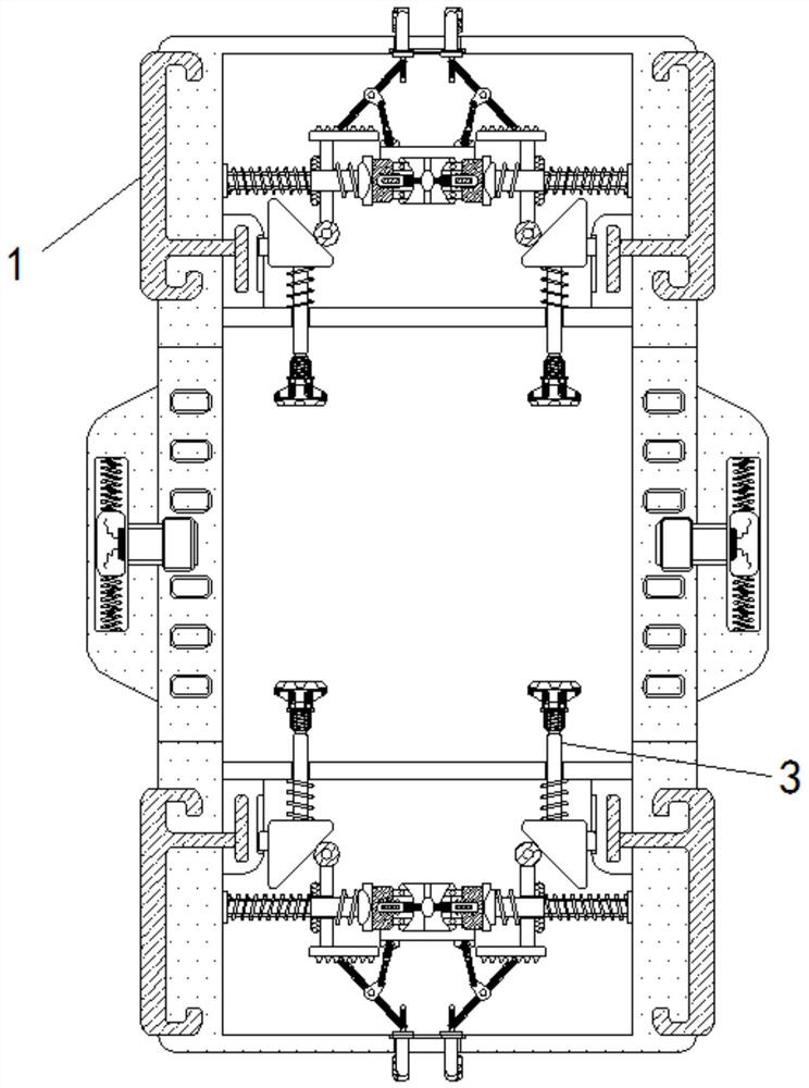
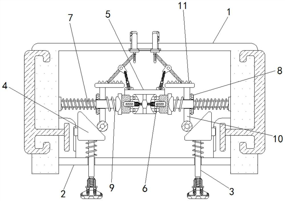
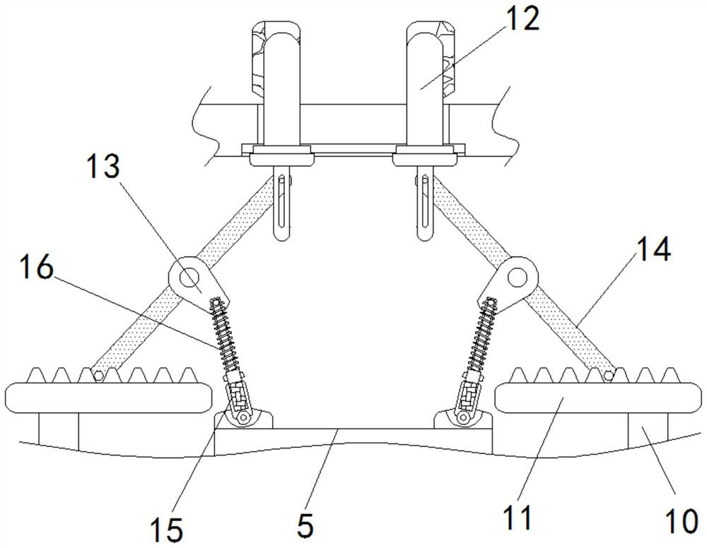
[0022] see Figure 1-5 , a boom vibration measuring device for a crane, comprising a housing 1, a positioning plate adapted to a wedge-shaped slider 4 is fixedly connected to the side wall of the inner cavity of the housing 1, and a pair of wedge-shaped sliders 4 are arranged on the positioning plate The chute for limiting, the upper and lower parts of the inner cavity of the housing 1 are fixed with a symmetrical protective plate 2, and a symmetrical abutment...


PUM


Abstract

The invention relates to the technical field of cranes, and discloses a big arm vibration measuring device for a crane. The big arm vibration measuring device comprises a shell, the upper part and thelower part of the inner cavity of the shell are both fixedly provided with symmetrical protection plates, and symmetrical abutting rods are slidably inserted into the protection plates; and the end,away from the center of the shell, of each abutting rod is fixedly connected with a wedge-shaped sliding block, and positioning blocks are fixedly installed at the top and the bottom of the shell correspondingly. According to the big arm vibration measuring device for the crane, the shell is arranged on the surface of a measured object, an electromagnet is used for driving a magnet ring to drive aguide rod to move, the abutting rod part is extruded to be connected and fixed, and the abutting rod part can be separated from the measured object without resetting under the action of a toothed plate, a rotating rod, an extrusion spring and the like; and a photosensitive resistor and an indicating lamp are used in cooperation to measure the vibration quantity, so that the stability of fixationon a measured object is effectively improved, and the effect of vibration measurement is effectively improved.

Description

technical field [0001] The invention relates to the technical field of cranes, in particular to a boom vibration measuring device for cranes. Background technique [0002] At present, during the operation of the crane, the boom of the crane will experience a certain degree of mechanical vibration, and when the frequency of the mechanical vibration exceeds the allowable vibration value, it will cause a large swing at the lifting end, making the lifting unsafe, and Long-term over-frequency vibration will lead to the gradual failure and damage of related parts, which will cause hidden dangers to the safety of the machine. Therefore, it is necessary to regularly use the relevant vibration measurement device to measure the vibration data of the running arm, but the general measurement device is in use. , its self-fixation is not stable enough, the connection with the measurement object is poor, and it is easy to cause relative vibration with the measurement object, which makes th...

Claims


Application Information

Patent Timeline
Patent Type & Authority Applications(China)
IPC IPC(8): G01H9/00B66C15/00
CPCB66C15/00G01H9/00
Inventor 徐强强
Owner 徐强强
Why Eureka
Try Eureka