LED lamp bead and dispensing method thereof

A technology of LED lamp beads and LED chips, which is applied in the direction of electrical components, circuits, semiconductor devices, etc., can solve the problems of large man-hours, complicated installation methods, and low production efficiency, so as to improve luminous efficiency and solve multiple excitation problems. Effect

Inactive Publication Date: 2021-01-22
江西瑞晟光电科技有限公司
View PDF3 Cites 0 Cited by
  • Summary
  • Abstract
  • Description
  • Claims
  • Application Information

AI Technical Summary

Problems solved by technology

This installation method is complicated and requires a lot of man-hours, resulting in low production efficiency and increased production costs. Moreover, the existing white light products use blue light chips and phosphors to excite and mix to emit white light. During the manufacturing process of LED lamp beads, Mix the yellow-green phosphor with the red phosphor for sealing, and the luminescent mechanism of the LED lamp bead is that after the blue chip emits blue light, part of the blue light excites the yellow-green phosphor to emit yellow-green light, and part of the red phosphor excites to emit red light, and then blue light The blue light emitted by the chip is mixed with the red light and yellow-green light emitted by the blue-light-excited phosphor to form white light; however, since the yellow-green phosphor and the red phosphor are mixed and sealed, in the actual light-emitting process, the blue-light-excited yellow-green phosphor emits Yellow-green light, the excited yellow-green light will excite the red phosphor to emit red light, so that the excited yellow-green phosphor repeatedly excites the red phosphor, resulting in multiple excitations, which in turn reduces the overall light efficiency of the LED lamp bead

Method used


Image

  • LED lamp bead and dispensing method thereof

Examples


Embodiment

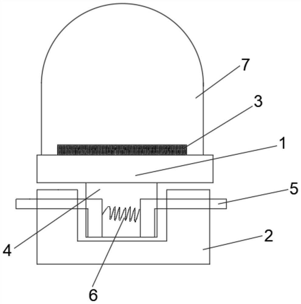
[0024] Such as figure 1 As shown, the present invention provides an LED lamp bead and a dispensing method thereof,

[0025] It includes a lamp bead holder 1 and a base 2, the lamp bead holder 1 is provided with an LED chip 3, the base 2 is provided with a square groove, and the lamp bead holder 1 is plugged into the square groove Inside, the two opposite inner walls of the square groove are provided with limiting grooves, and the lamp bead holder 1 is provided with a cavity 4 inside, and the interior of the cavity 4 is provided with a spacer corresponding to the limiting groove. The limit mechanism includes two symmetrically arranged L-shaped limit blocks 5, and the horizontal ends of the two limit blocks 5 respectively pass through the cavity 4 and extend to the inside of the two limit grooves A spring 6 is fixedly connected to the side walls adjacent to the vertical ends of the two limiting blocks 5, and the two opposite outer walls of the base 2 are provided with operation...


PUM


Abstract

The invention discloses an LED lamp bead and a dispensing method thereof. TheLED lamp bead comprises a lamp bead fixing seat and a base, an LED chip is arranged in the lamp bead fixing seat, the lampbead fixing seat is connected to the base in an inserted mode, limiting grooves are formed in the two opposite inner side walls of a square groove, a cavity is formed in the lamp bead fixing seat, anda limiting mechanism corresponding to the limiting grooves is arranged in the cavity; the limiting mechanism comprises two symmetrically-arranged L-shaped limiting blocks, the side walls, close to each other, of the vertical ends of the two limiting blocks are jointly and fixedly connected with a spring, and the two opposite outer side walls of the base are each provided with an operation groovecommunicated with the cavity. When the LED chip or the lamp bead fixing seat needs to be replaced or maintained, by arranging the limiting mechanism, an operator manually enables fingers to penetratethrough the two operation grooves and enables the two limiting blocks to move close to each other, and when the horizontal ends of the limiting blocks are separated from the limiting grooves, the lampbead fixing seat can be easily separated from the base; therefore, the purpose of replacing or maintaining the LED chip or the lamp bead fixing seat is achieved.

Description

technical field [0001] The invention relates to the technical field of LED dispensing, in particular to an LED lamp bead and a dispensing method thereof. Background technique [0002] Today, with the development of modern China, emerging products in various industries are gradually modernized. Take the lighting industry as an example. The previous light bulbs, incandescent lamps, and fluorescent lamps have been gradually replaced by modern energy-saving lamps, LED lamps and other more energy-saving and environmentally friendly lighting fixtures. With the development of science and technology and the further deepening of application practice, LED lighting technology has become the most popular, most promising and most acceptable lighting technology. With the continuous improvement of LED demand, its welding work has increased relatively. At present, LED lights The bead installation technology is usually to insert the two pins of the straw hat type LED lamp bead into the subs...

Claims


Application Information

Patent Timeline
Patent Type & Authority Applications(China)
IPC IPC(8): H01L33/48H01L33/50H01L33/52
CPCH01L33/483H01L33/504H01L33/52H01L2933/0033H01L2933/0041H01L2933/005
Inventor 李仁
Owner 江西瑞晟光电科技有限公司
Why Eureka
Try Eureka