Ship tail gas decomposing device

A technology for exhaust gas and ships, applied in exhaust devices, noise reduction devices, exhaust treatment, etc., can solve problems such as acidification of soil and water sources, refractory lungs, and harm to human health

Pending Publication Date: 2021-03-09
饶开亮
View PDF5 Cites 0 Cited by
  • Summary
  • Abstract
  • Description
  • Claims
  • Application Information

AI Technical Summary

Problems solved by technology

While directly endangering human health, these pollutants will also have a profound impact on the human living environment. For example, carbon dioxide has a strong pungent smell. When it reaches a certain concentration, it will easily lead to acid rain, acidify soil and water sources, and affect crops and forests. growth
In addition, a large amount of waste heat contained in the exhaust gas is not used, resulting in the urban heat island effect
[0006] What's more serious, ship exhaust has adverse effects on the human body. For example, some solid particles and filamentous particles cannot be discharged out of the lungs. As long as you work for a few hours, there will be dust in the mouth and nose of the human body. Pollutants full of black oil can cause lung inflammation, fever, sneezing and nasal congestion, etc., which are difficult to cure, such as: the recent new type of pneumonia, some people with lung problems are difficult to heal, coupled with the population of industrial cities Miji, many big cities have this phenomenon

Method used


Image

  • Ship tail gas decomposing device
  • Ship tail gas decomposing device
  • Ship tail gas decomposing device

Examples


Embodiment Construction

[0022] The following will clearly and completely describe the technical solutions in the embodiments of the present invention with reference to the accompanying drawings in the embodiments of the present invention. Obviously, the described embodiments are only some, not all, embodiments of the present invention. Based on the embodiments of the present invention, all other embodiments obtained by persons of ordinary skill in the art without making creative efforts belong to the protection scope of the present invention.

[0023] Unless otherwise defined, all technical and scientific terms used herein have the same meaning as commonly understood by one of ordinary skill in the technical field of the invention. The terms used herein in the description of the present invention are for the purpose of describing specific embodiments only, and are not intended to limit the present invention.

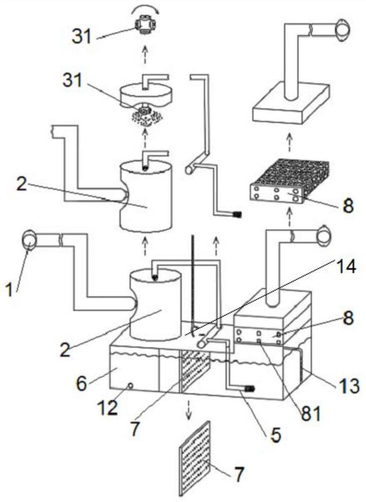
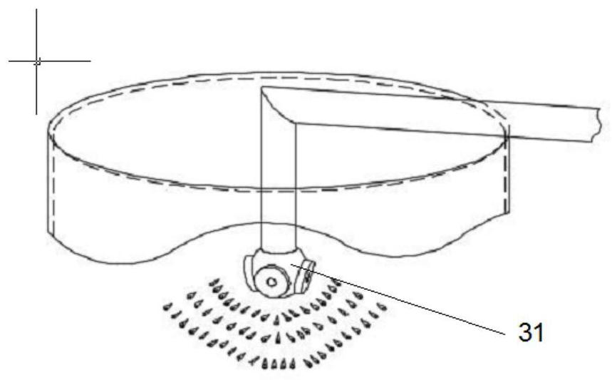
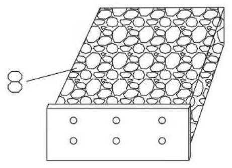
[0024] Figure 1 ~ Figure 3 Schematically shows the structure of a ship tail gas decomposi...


PUM


Abstract

The invention discloses a ship tail gas decomposing device. Tail gas exhausted by a ship can enter a shell from a machine connecting body, meanwhile, a high-pressure water pump can pump a vehicle ureasolution in the shell through a second pipeline, the vehicle urea solution is discharged into the shell through a first pipeline, the vehicle urea solution discharged into the shell can absorb the tail gas exhausted by the ship, and the vehicle urea solution absorbing the tail gas falls on the lower end of the shell; and due to the fact that the lower end of the shell communicates with one side of the shell, a refrigerating machine condensation plate is installed in the middle of a liquid storage tank, the ship tail gas, cooled vehicle urea and an anti-freezing solution are fully mixed, and anitrogen acid beverage is produced according to the requirement. Therefore, the vehicle urea solution can enter a cavity of the shell, the vehicle urea solution is recycled, and the vehicle urea solution can reduce harmful substances in the ship tail gas; and in addition, the tail gas absorbing the harmful substances can enter the shell and is finally discharged to a filter connector through a sponge filter screen. Through the sponge filter screen, the sponge filter screen can filter air impurities and water, the harmful substances in the ship tail gas can be further reduced, and the discharge amount of the ship tail gas is reduced. The ship tail gas enters a ship engine filter to be mixed with air, the ship tail gas enters a combustion chamber to do work circularly, the tail gas is not discharged, and environmental protection is achieved.

Description

technical field [0001] The invention belongs to the technical field of ship tail gas treatment, and in particular relates to a ship tail gas dissolving device. Background technique [0002] The ship is one of the oldest means of transportation, and it has made great contributions to the development of mankind. With the development of society, the tonnage of the ship is increasing, the horsepower is increasing, and the displacement is also increasing, such as warships, Cargo ships, passenger ships and airboats, etc. [0003] The fuel consumption of ships is huge, so they emit more exhaust gas. For example, in places such as the three cities of Wuhan and the Huangpu River in Shanghai, ships on the coastline emit a large amount of exhaust gas, which is no less than that of cars. After a large amount of exhaust gas is discharged, there will be more serious problems, such as: air pollution, river and sea pollution, etc. The exhaust gas discharged from ships contains hydrocarbon...

Claims


Application Information

Patent Timeline
Patent Type & Authority Applications(China)
IPC IPC(8): F01N3/033F01N3/08F01N3/022
CPCF01N3/0222F01N3/0807F01N3/0821F01N2590/02F01N2610/02F01N2610/1486
Inventor 饶开亮饶定康饶蔚骏熊道美李东华饶阳
Owner 饶开亮
Why Eureka
Try Eureka