

Internet of Things data security signal transmission system
Patent Information
- Authority / Receiving Office
- CN · China
- Current Assignee / Owner
- 上海敏桥信息科技有限公司
- Publication Date
- 2021-01-22
Smart Images
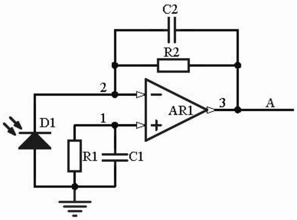
Figure 1 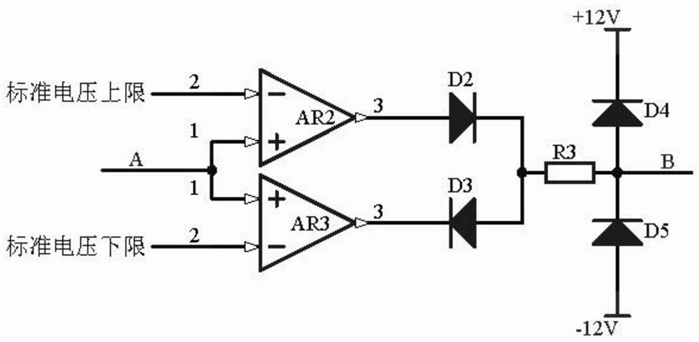
Figure 2 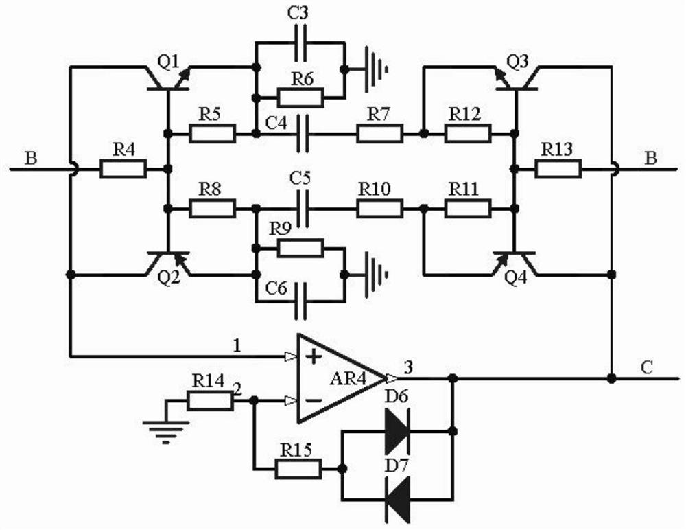
Figure 3
Abstract
Description
technical field
[0001] The invention relates to the technical field of data security, in particular to an Internet of Things data security signal transmission system. Background technique
[0002] At present, the radio and television Internet of things has developed into an era dominated by optical fiber networks. With the sharp drop in the price of 1550nm optical transmitters and erbium-doped fiber amplifiers EDFA, 1550nm optical transmission technology has been widely used. However, in 1550nm optical transmission networks , when the optical power of the optical signal injected by the optical transmitter into the optical fiber is too low, the optical signal will be greatly attenuated during long-distance transmission, and data packet loss will easily occur; when the optical signal injected by the optical transmitter into the optical fiber When the power is higher than the SBS threshold, the stimulated Brillouin scattering (SBS) phenomenon will occur, the optical signal inde...