
An Internet of Things data security signal transmission system

A signal transmission system and data security technology, applied in the field of IoT data security signal transmission system, can solve the problems of chromatic dispersion, affecting the security performance of data transmission, optical signal waveform distortion, etc.

Active Publication Date: 2021-05-04
上海敏桥信息科技有限公司
View PDF3 Cites 0 Cited by
  • Summary
  • Abstract
  • Description
  • Claims
  • Application Information

AI Technical Summary

Problems solved by technology

[0002] At present, the radio and television Internet of things has developed into an era dominated by optical fiber networks. With the sharp drop in the price of 1550nm optical transmitters and erbium-doped fiber amplifiers EDFA, 1550nm optical transmission technology has been widely used. However, in 1550nm optical transmission networks , when the optical power of the optical signal injected by the optical transmitter into the optical fiber is too low, the optical signal will be greatly attenuated during long-distance transmission, and data packet loss will easily occur; when the optical signal injected by the optical transmitter into the optical fiber When the power is higher than the SBS threshold, the stimulated Brillouin scattering (SBS) phenomenon will occur, the optical signal index will drop sharply, and it will cause serious dispersion in the long distance, which will distort the optical signal waveform and cause intersymbol crosstalk. Therefore, when the optical When the optical power injected by the transmitter into the optical fiber is too high or too low, the quality of the optical signal will be reduced and the security performance of data transmission will be affected.

Method used


Image

  • An Internet of Things data security signal transmission system
  • An Internet of Things data security signal transmission system
  • An Internet of Things data security signal transmission system

Examples


Embodiment Construction

[0014] Regarding the aforementioned and other technical contents, features and effects of the present invention, refer to the appended figure 1 to attach Figure 4 It will be apparent from the detailed description of the embodiments. The structural contents mentioned in the following embodiments are all based on the accompanying drawings of the description.

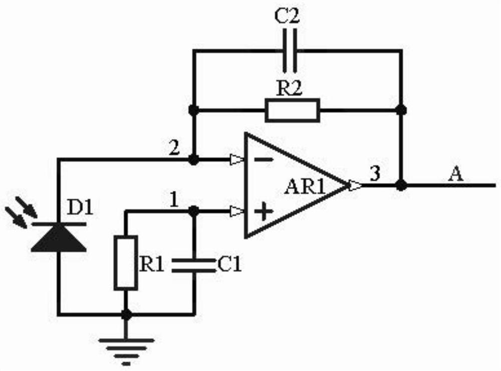
[0015] In order to convert the input optical power of the radio and television Internet of Things optical transmitter into an input optical voltage with sufficient amplitude for comparison, a photoelectric conversion amplifier circuit is used to sample the input optical signal of the optical transmitter by using the PIN photodiode D1, and the PIN photoelectric Diode D1 will generate a photocurrent proportional to the illuminance under the illumination of the optical signal entering the fiber from the optical transmitter, and convert the photocurrent generated by the PIN photodiode D1 into the optical voltage entering the...


PUM


Abstract

The invention discloses a data security signal transmission system of the Internet of Things, which includes a photoelectric conversion amplifier circuit, a voltage comparison circuit, a sine wave oscillation circuit and a frequency modulation transmission circuit. The signal is sampled and its optical power is converted into a fiber optic voltage. The voltage comparison circuit compares the fiber optic voltage with the upper limit of the standard voltage and the lower limit of the standard voltage. The power detection signal is obtained, the sine wave oscillation circuit determines the frequency of the sine wave modulation signal according to the positive and negative of the power detection signal, and the frequency modulation transmitting circuit performs FM modulation on the sine wave modulation signal to obtain the power conditioning signal, and transmits the power conditioning signal to the radio and television material Network power monitoring and control terminal, so that the radio and television Internet of Things power monitoring and control terminal can adjust the optical power of the radio and television Internet of Things optical transmitter.

Description

technical field [0001] The invention relates to the technical field of data security, in particular to an Internet of Things data security signal transmission system. Background technique [0002] At present, the radio and television Internet of things has developed into an era dominated by optical fiber networks. With the sharp drop in the price of 1550nm optical transmitters and erbium-doped fiber amplifiers EDFA, 1550nm optical transmission technology has been widely used. However, in 1550nm optical transmission networks , when the optical power of the optical signal injected by the optical transmitter into the optical fiber is too low, the optical signal will be greatly attenuated during long-distance transmission, and data packet loss will easily occur; when the optical signal injected by the optical transmitter into the optical fiber When the power is higher than the SBS threshold, the stimulated Brillouin scattering (SBS) phenomenon will occur, the optical signal inde...

Claims


Application Information

Patent Timeline
Patent Type & Authority Patents(China)
IPC IPC(8): H04B10/556H04B10/564H04B10/2575H04B10/079
CPCH04B10/07953H04B10/07955H04B10/2575H04B10/5563H04B10/564
Inventor 王秀芳唐有钢
Owner 上海敏桥信息科技有限公司
Learn More