Standing long jump body measurement equipment based on machine vision

A machine vision and long jump technology, applied in gymnastics equipment, jumping equipment, sports accessories, etc., can solve problems such as complex layout, poor detection accuracy, and low detection efficiency, and achieve simple operation structure, convenience, practicality, and application good sex effect

Pending Publication Date: 2021-01-26
JIANGSU FENGHUANG INTELLIGENT EDUCATION RES INST CO LTD
View PDF0 Cites 1 Cited by
  • Summary
  • Abstract
  • Description
  • Claims
  • Application Information

AI Technical Summary

Benefits of technology

This patented technology allows users to measure their body movements more accurately than previous methods like measuring weight or length. By utilizing an image processing system called CMOS cameras, these measurements are made easier compared to older methods that require multiple trials at varying levels. Additionally, they have been developed through programming machines that allow them to record videos from specific angles while also allowing trialers to easily find relevant images within each section. Overall, this new method simplifies the process of conducting tests and makes it faster and cheaper.

Problems solved by technology

The technical problem addressed in this patented text relating to current standby length jumps testing devices that rely heavily on human judgment can be attributed to their complexity or lacking precision during analysis due to factors like positional variations caused by gravity. This results in lowered overall effectiveness compared with more automated systems such as video monitoring.

Method used


Image

  • Standing long jump body measurement equipment based on machine vision
  • Standing long jump body measurement equipment based on machine vision
  • Standing long jump body measurement equipment based on machine vision

Examples


Embodiment Construction

[0028] The following will clearly and completely describe the technical solutions in the embodiments of the present invention with reference to the accompanying drawings in the embodiments of the present invention. Obviously, the described embodiments are only some, not all, embodiments of the present invention. Based on the embodiments of the present invention, all other embodiments obtained by persons of ordinary skill in the art without making creative efforts belong to the protection scope of the present invention.

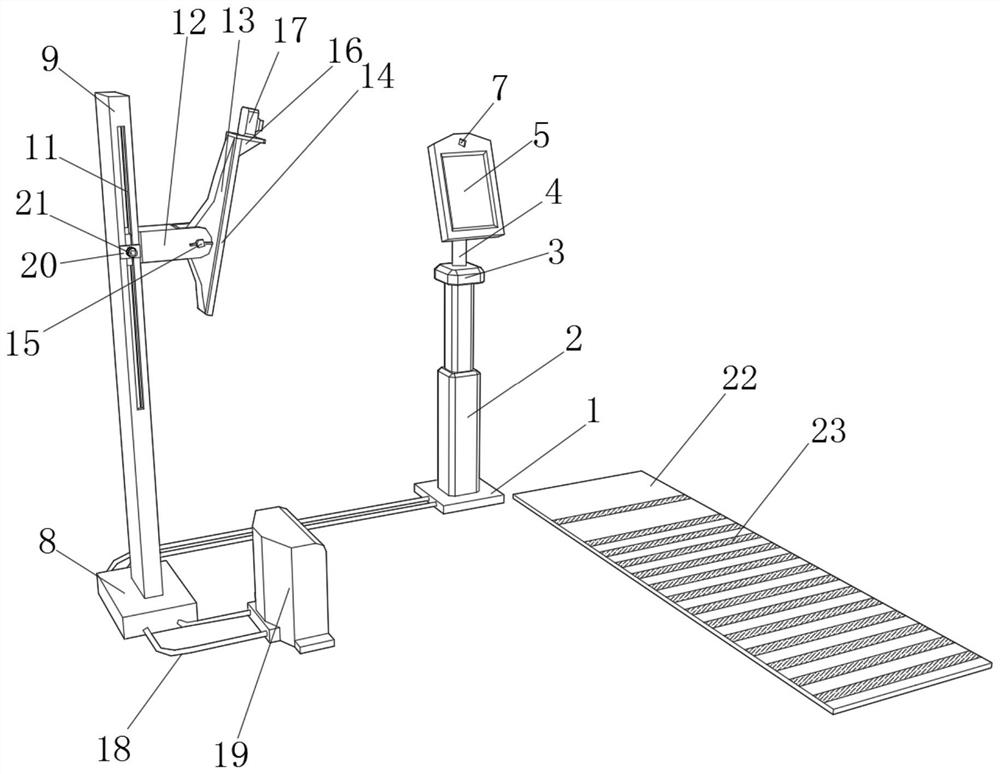
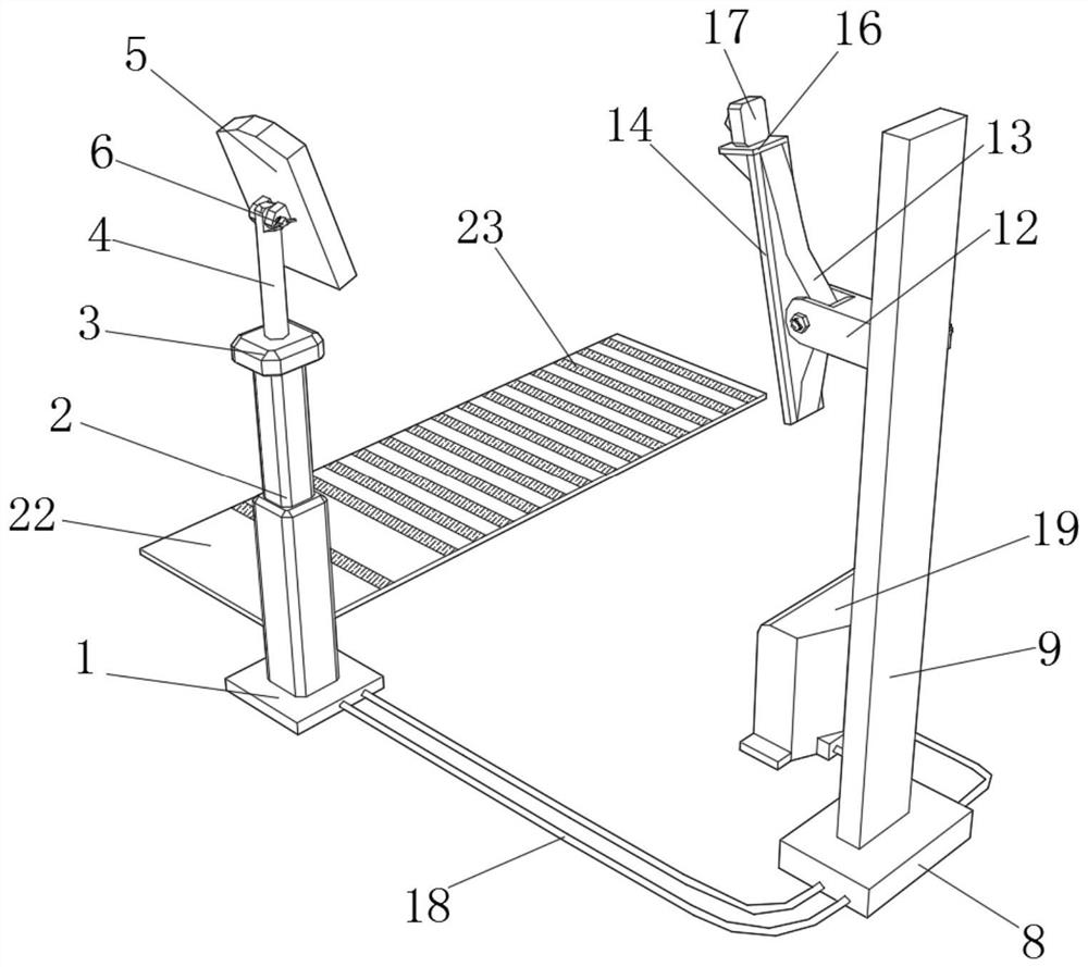
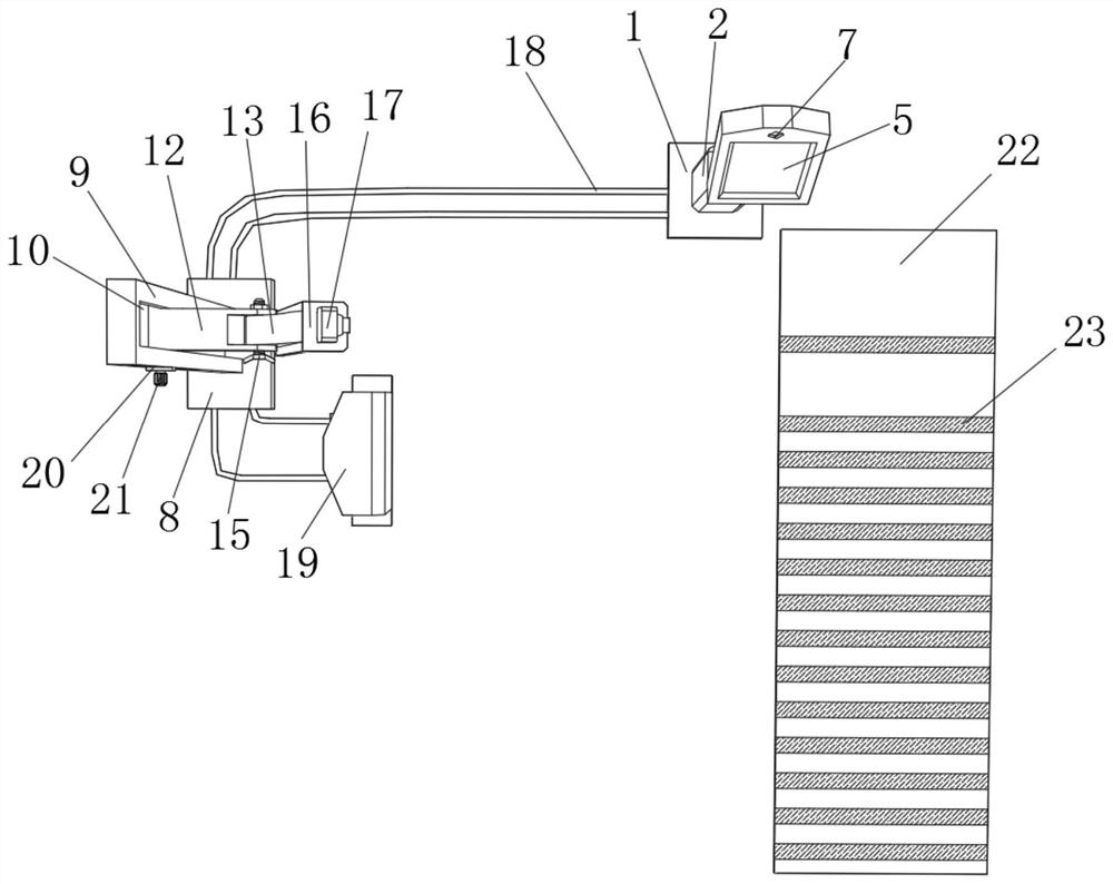
[0029] refer to Figure 1-Figure 4 , a standing long jump physical measurement device based on machine vision, comprising a first base 1, a second base 8, an Android client control terminal, a long jump pad 22 and a server terminal, the upper surface of the second base 8 is fixed with a mounting plate 9 by bolts , the second base 8 plays the role of installing the mounting plate 9, one side of the mounting plate 9 is provided with a chute 10, one side of the c...


PUM


Abstract

The invention relates to the technical field of standing long jump automatic evaluation, and discloses standing long jump body measurement equipment based on machine vision. The equipment comprises afirst machine base, a second machine base, an Android client control end, a long jump pad and a server terminal, and is characterized in that the upper surface of the second machine base is fixedly connected with a mounting plate, one side of the mounting plate is provided with a sliding groove, a sliding rod is movably connected to one side of the sliding groove, a rotating plate is movably connected to one side of the sliding rod, a second claw bolt is movably connected to one side of the rotating plate, a fixing plate is fixedly connected to one side of the rotating plate, a mounting tableis fixedly connected to the upper surface of the fixing plate, a second camera is embedded into one side of the mounting table, and the Android client control terminal is connected with the second camera through a signal line. According to the invention, an examinee is reminded of ending after an effective landing frame is positioned and recording is completed, the operation structure is simple, autonomous testing is facilitated, the labor cost is reduced, convenience and rapidness are achieved, the detection precision is accurate, and the detection efficiency is improved.

Description


Claims


Application Information

Patent Timeline
Owner JIANGSU FENGHUANG INTELLIGENT EDUCATION RES INST CO LTD
Why Eureka
Try Eureka