Bearing mounting tool

A tooling and bearing technology, applied in the field of bearing installation, can solve problems such as small scope of application, and achieve the effects of improving efficiency, facilitating adjustment and reducing costs

Active Publication Date: 2021-01-26
冠县恒祥轴承制造有限公司
View PDF5 Cites 0 Cited by
  • Summary
  • Abstract
  • Description
  • Claims
  • Application Information

AI Technical Summary

Problems solved by technology

When in use, it can only press the end face of the bearing to be flush with the end face of the parts to be assembled, an

Method used


Image

  • Bearing mounting tool
  • Bearing mounting tool
  • Bearing mounting tool

Examples


Example Embodiment

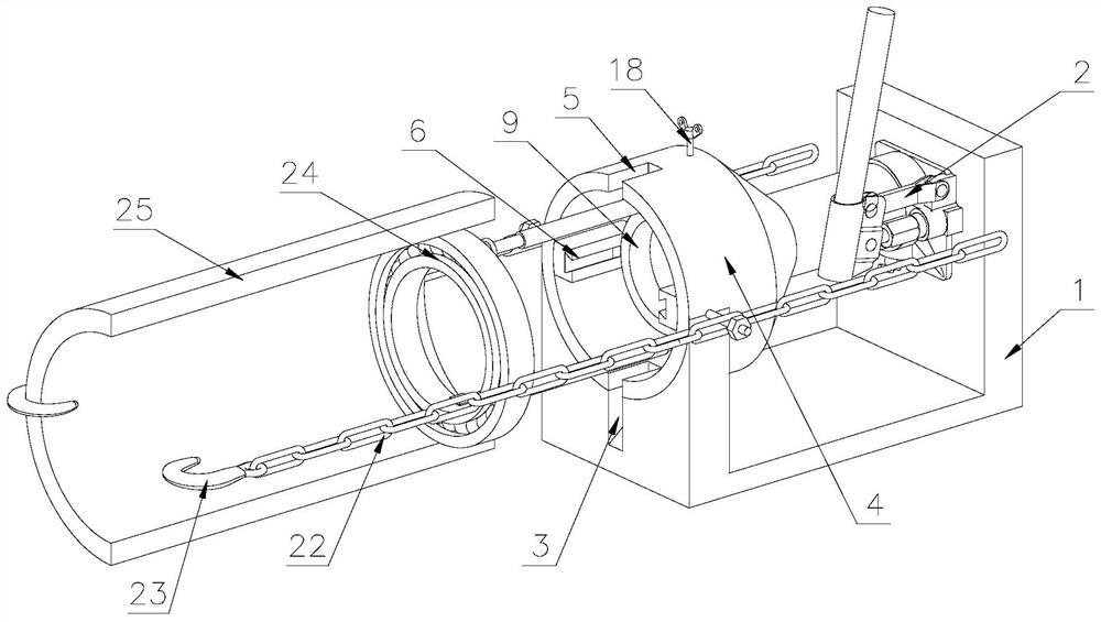
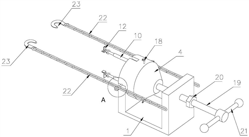
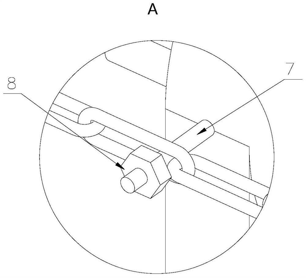
[0036]Attached belowFigure 1-6The technical solutions in the embodiments of the present invention are described clearly and completely. Obviously, the described embodiments are only a part of the embodiments of the present invention, rather than all the embodiments. Based on the embodiments of the present invention, all other embodiments obtained by those of ordinary skill in the art without creative work shall fall within the protection scope of the present invention.

[0037]In the description of the present invention, it should be understood that the terms "longitudinal", "lateral", "upper", "lower", "front", "rear", "left", "right", "vertical", The orientation or positional relationship indicated by "horizontal", "top", "bottom", "inner", "outer", etc. are based on the orientation or positional relationship shown in the drawings, and are only for the convenience of describing the present invention, rather than indicating or It is implied that the device or element referred to must ...


PUM


Abstract

The invention discloses a bearing mounting tool. The bearing mounting tool comprises a U-shaped base, an ejection mechanism and a fixed cylinder, wherein the fixed cylinder is fixedly mounted at one end of the U-shaped base; a top base is arranged in the fixed cylinder; one end of the ejection mechanism is fixedly mounted on the side wall of the U-shaped base, and the other end is fixedly connected with the top base; the ejection mechanism is a hydraulic jack or a screw rod; when the ejection mechanism is the hydraulic jack, the ejection mechanism is fixedly connected with one end of the fixedcylinder; when the ejection mechanism is the screw rod, the ejection mechanism is in threaded connection with one end of the fixed cylinder, and a handle is arranged at one end of the screw rod; anda plurality of ejector rods are symmetrically arranged on one side of the top base, and at least two ejector rods are provided. The ejection mechanism is arranged on one side of the top base, and themultiple ejector rods are symmetrically arranged on the other side of the top base; the ejection mechanism is used for driving the top base to slide to transfer acting force to the ejector rods; and the ejector rods press bearings into parts to be assembled, so that the bearing mounting tool is specifically suitable for assembly of the bearings in shaft sleeve parts.

Description

Technical field[0001]The invention belongs to the technical field of bearing installation, and particularly relates to a bearing installation tool.Background technique[0002]In the industrial production process, we often encounter the situation of assembling bearings into bushing parts. The assembly of the bearings was originally carried out by manual labor, using the method of using a copper hammer to strike the bearing along the outer ring of the bearing. When assembling the bearing in this way, due to the partial contact between the copper hammer and the bearing and uneven force, the bearing is prone to tilt. In addition, because it is manually knocked, it is inevitable that knocking will occur. Once this happens, the copper hammer will knock on the inner ring of the bearing or on the shaft sleeve. If the copper knocks on the inner ring of the bearing, the force generated by the knock will pass through the rolling elements of the bearing. If it is transmitted to the outer ring, it...

Claims


Application Information

Patent Timeline
IPC IPC(8): B25B27/06
CPCB25B27/06B25B27/062B25B27/064
Inventor 崔振庆
Owner 冠县恒祥轴承制造有限公司
Why Eureka
Try Eureka