Screw protection tool

A screw and tooling technology, applied in the field of screw protection tooling, to avoid loose connection

Pending Publication Date: 2021-01-26
HUNAN LIANCHENG TRACK EQUIP CO LTD
View PDF0 Cites 0 Cited by
  • Summary
  • Abstract
  • Description
  • Claims
  • Application Information

AI Technical Summary

Problems solved by technology

[0004] The purpose of the present invention is to provide a screw protection tool to solve the problem of protecting the extension screw on the transformer oil tank

Method used


Image

  • Screw protection tool
  • Screw protection tool
  • Screw protection tool

Examples


Embodiment 1

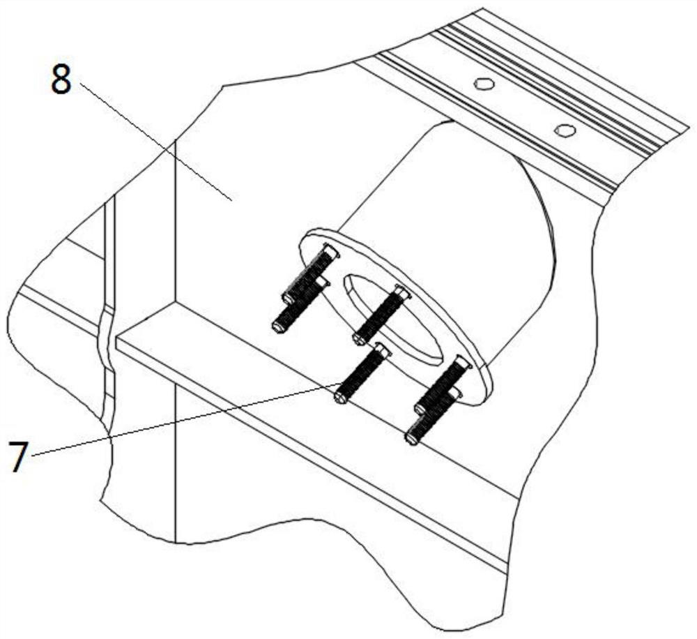
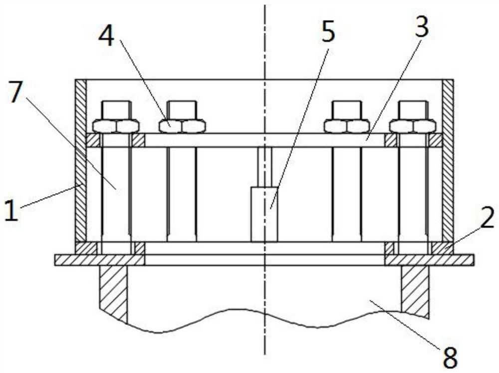
[0036] see Figure 2 to Figure 3 , a screw protective tooling, this embodiment is applied to the protection of the extension screw of the lifting seat of the transformer oil tank.

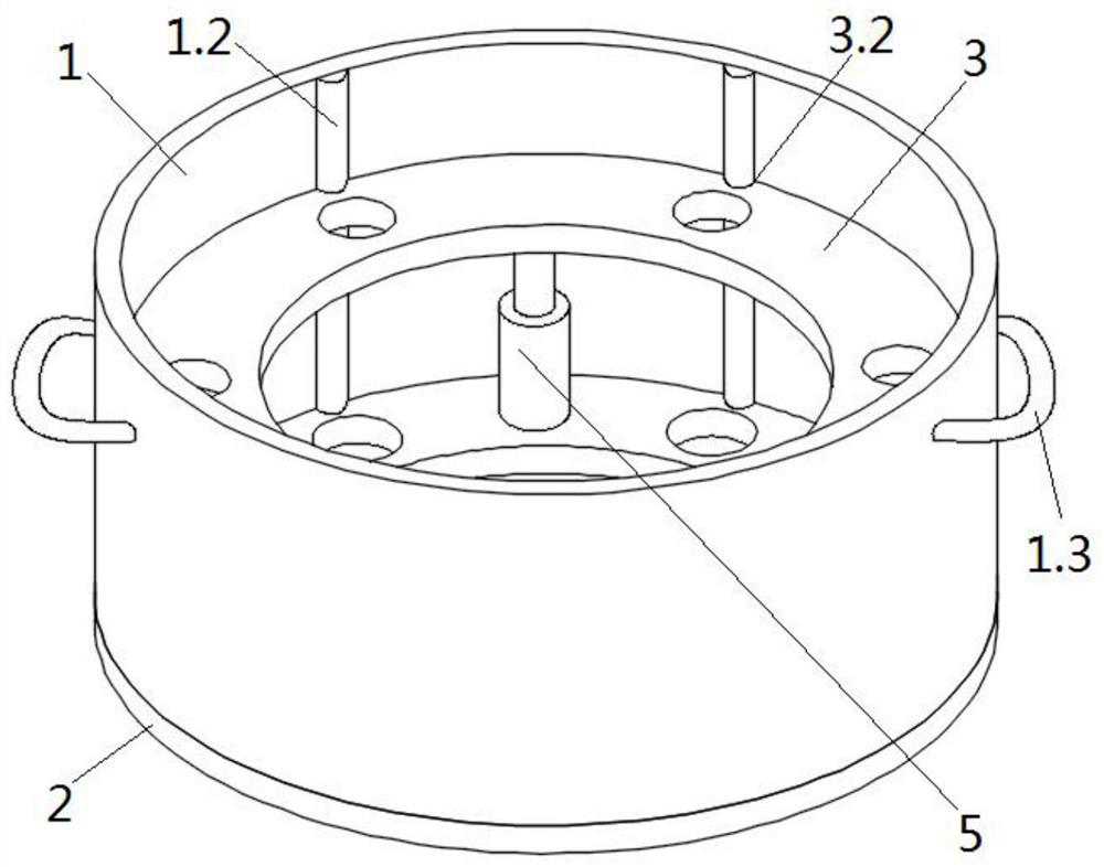
[0037] A kind of screw protective tooling, including a first casing 1, a first partition 2, a second partition 3 and a fixing nut 4 for connecting a screw 7; the first partition 2 and the second partition 3 are along the first A casing 1 is arranged in the axial direction, the plate surface of the first partition 2 is parallel to the plate surface of the second partition 3, and both the first partition 2 and the second partition 3 are provided with insertable screw rods. 7 through holes, since the number of screw rods 7 on the transformer oil tank 8 is six, the first partition plate 2 and the second partition plate 3 are provided with six through holes, and the positions correspond to the positions of the screw rods 7 to be protected one by one. ; The combination of the first casing 1, the first d...

Embodiment 2

[0045] The difference between this embodiment and Embodiment 1 is that a chute 1.1 is provided on the inner wall of the first casing 1, and a sliding tooth 3.1 corresponding to the chute 1.1 is provided on the second partition 3, as Figure 4 shown.

Embodiment 3

[0047] The difference between this embodiment and embodiment 1 is that sliding mechanisms such as chute 1.1, sliding tooth 3.1, slide rail 1.2 and groove 3.2 are not provided between the second partition 3 and the first casing 1, and the first partition 2 and No expansion part 5 is set between the second partitions 3, and the screw protective tooling in this embodiment also includes a second casing 6, the top of the second casing 6 is connected with the second partition 3; The casing 6 is movably connected with the first partition 2, can move along the axial direction of the first partition 2, adjust the distance between the first partition 2 and the second partition 3, and realize the protection of the screws 7 with different lengths. Simultaneously, the bottom of the second casing 6 stretches into the rising seat of the transformer oil tank 8, so that the external force that the protective tooling is subjected to can be transmitted to the casing of the transformer oil tank. ...


PUM


Abstract

The invention provides a screw protection tool. The screw protection tool comprises a first pile casing, a first partition plate, a second partition plate and fixed nuts used for being connected witha screw. The first partition plate and the second partition plate are arranged in the axial direction of the first pile casing, the plate face of the first partition plate is parallel to the plate face of the second partition plate, the first partition plate and the second partition plate are provided with through holes where the screw can be inserted, and the first pile casing, the first partition plate and the second partition plate are combined to form protection space of the screw. The first partition plate is connected with one end of the first pile casing. The second partition plate is arranged in the first pile casing and can move in the axial direction of the first pile casing. The screw and the protection tool are locked through the fixed nuts, the protection tool can be assembledon an extension screw of a transformer oil tank, and the screw is protected against screw deformation and damage caused by external force damage in the transferring and production processes; and thesecond partition plate can move in the axial direction of the first pile casing, and protection to screws of different length specifications can be achieved.

Description

technical field [0001] The invention relates to the technical field of equipment protection, in particular to a screw protection tool. Background technique [0002] There is a rising seat on the transformer oil tank, and a screw rod for assembling with other parts is arranged on the rising seat, such as figure 1 As shown; a screw with a length of 55mm and a diameter of 10mm is welded on the raised seat along the circumferential direction of the raised seat. Because there is no effective protection for the screw, during the process of lifting, sanding, and spraying the transformer oil tank body , The screw rod on the rising seat is easily bent, deformed and damaged, resulting in the need to rework the transformer box, affecting product quality and production process. [0003] To sum up, there is an urgent need for a screw protection tool to solve the problems in the prior art. Contents of the invention [0004] The purpose of the present invention is to provide a screw pr...

Claims


Application Information

Patent Timeline
IPC IPC(8): F16B41/00
CPCF16B41/002
Inventor 彪伟全鹏江禄卿
Owner HUNAN LIANCHENG TRACK EQUIP CO LTD
Why Eureka
Try Eureka