Virus storage tank antivirus and inactivation device for virus protection
A technology for storage tanks and viruses, which is applied in the field of antivirus and inactivation devices for virus storage tanks for virus protection, can solve the problems of low work efficiency and labor, and achieve the effect of high work efficiency
- Summary
- Abstract
- Description
- Claims
- Application Information
AI Technical Summary
Problems solved by technology
Method used
Image

Examples
Embodiment 1
[0027] A virus storage tank antivirus and inactivation device for virus protection, such as Figure 1-Figure 4 As shown, it includes a bottom plate 1, a housing 2, a placement component 3 and a disinfection component 4. The top of the bottom plate 1 is fixed with a housing 2, the housing 2 is provided with a placement component 3, and the lower part of the housing 2 is provided with a disinfection component 4. The disinfection component 4 cooperates with the placement component 3 .
[0028]The placement assembly 3 includes a first support sleeve 301, a guide slide bar 302, a support plate 303, a handle 304, a fixed ring 305, a guide sleeve 306, a rotating rod 307, a placement frame 308, a sliding sleeve 309, a limit rod 3010 and a first The spring 3011, the first support sleeve 301 is fixedly connected to the right side of the lower part of the front and rear sides of the housing 2, and the first support sleeve 301 on the front and rear sides is slidably connected with guide s...
Embodiment 2
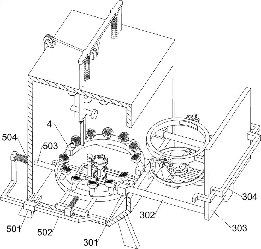
[0034] On the basis of Example 1, such as figure 1 , image 3 , Figure 4 , Figure 5 with Image 6 As shown, a moving assembly 5 is also included. The moving assembly 5 includes a second support sleeve 501, a special-shaped rod 502, a movable rod 503 and a third spring 504. The support sleeve 501 and the second support sleeve 501 are slidably connected with a special-shaped rod 502, and the special-shaped rod 502 is in contact with the lower part of the n-shaped sliding rod 402. Rod 503, movable rod 503 cooperates with guide slide bar 302, movable rod 503 left end is fixedly connected with special-shaped rod 502 inner left side surface top, is connected between the special-shaped rod 502 inner left side surface top and housing 2 outer left side Three springs 504 , the third spring 504 is sleeved on the movable rod 503 .
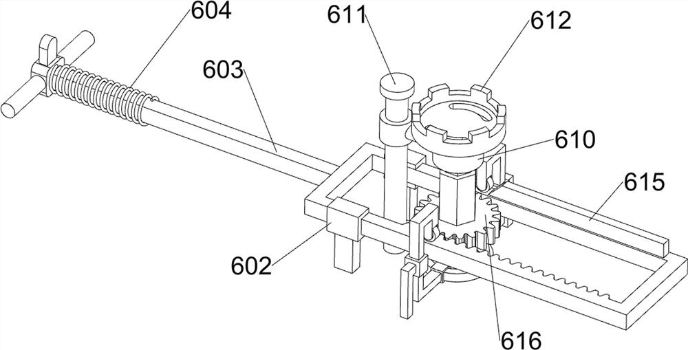
[0035] Also includes a rotating assembly 6, the rotating assembly 6 includes a first clutch block 601, a guide block 602, a toothed sliding frame 603, ...
Embodiment 3
[0039] On the basis of embodiment 1 and embodiment 2, such as figure 1 with Figure 7 As shown, a clamping assembly 7 is also included, and the clamping assembly 7 includes a movable frame 701, a wedge block 702, a sixth spring 703, a friction block 704 and a seventh spring 705, and the sliding type between the front and rear sides of the top of the housing 2 There is a movable frame 701 connected through the movable frame 701, and a sixth spring 703 is connected between the front and rear sides of the inner top of the movable frame 701 and the outer top of the housing 2, and the two ends of the lower part of the front side of the movable frame 701 are fixedly connected to the two ends of the lower part of the rear side. Wedge block 702 is arranged, and friction block 704 is slidably worn in the middle of the front and rear sides of fixed ring 305. The seventh spring 705 is also connected between the inner rear surface of the rear friction block 704 and the outer surface of t...
PUM
 Abstract
Description
Claims
Application Information