
Self-locking machining device for gas compressor rotor blade locking block

A technology of compressor rotor and processing device, applied in feeding device, positioning device, storage device, etc., can solve the problems of high speed of compressor rotor, loose bolts, no self-locking function, etc., to achieve self-locking function, Easy and convenient installation and replacement

Pending Publication Date: 2021-01-29
青岛中科国晟动力科技有限公司
View PDF0 Cites 0 Cited by
  • Summary
  • Abstract
  • Description
  • Claims
  • Application Information

AI Technical Summary

Problems solved by technology

The compressor rotor rotates at a high speed, and there is vibration. Under the action of various factors, the bolts on the compressor rotor blade lock block will be loosened.
[0003] Therefore, the lock block of the compressor rotor blade needs to have a self-locking function to adapt to the specific working conditions of the compressor. The lock block is extruded and deformed, so that the threaded part of the lock block is plastically deformed, so as to meet the specified self-locking torque requirements and realize the self-locking function

Method used


Image

  • Self-locking machining device for gas compressor rotor blade locking block
  • Self-locking machining device for gas compressor rotor blade locking block
  • Self-locking machining device for gas compressor rotor blade locking block

Examples


Embodiment Construction

[0034] Embodiments of the present invention will be described in detail below in conjunction with the accompanying drawings.

[0035] Embodiments of the present invention are described below through specific examples, and those skilled in the art can easily understand other advantages and effects of the present invention from the content disclosed in this specification. Apparently, the described embodiments are only some of the embodiments of the present invention, but not all of them. The present invention can also be implemented or applied through other different specific implementation modes, and various modifications or changes can be made to the details in this specification based on different viewpoints and applications without departing from the spirit of the present invention. It should be noted that, in the case of no conflict, the following embodiments and features in the embodiments can be combined with each other. Based on the embodiments of the present invention,...


PUM


Abstract

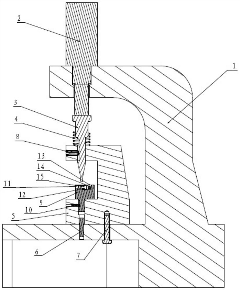
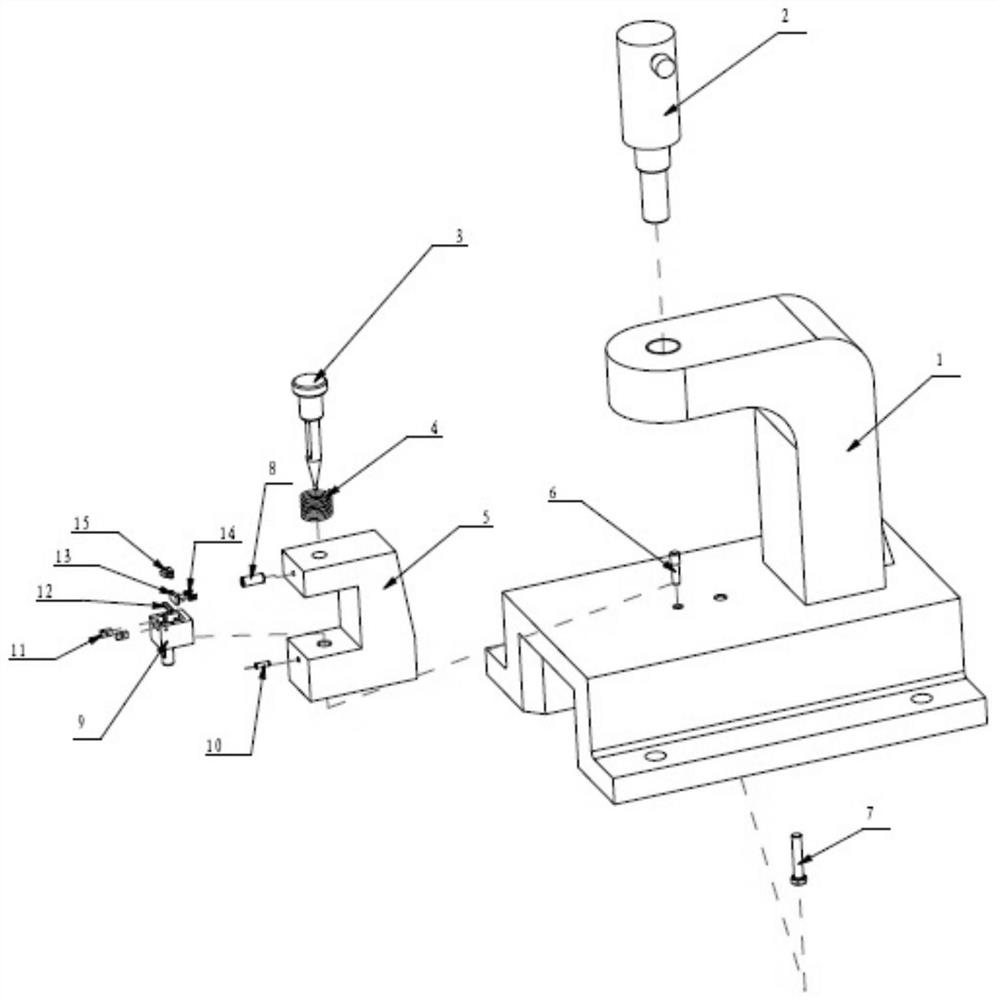
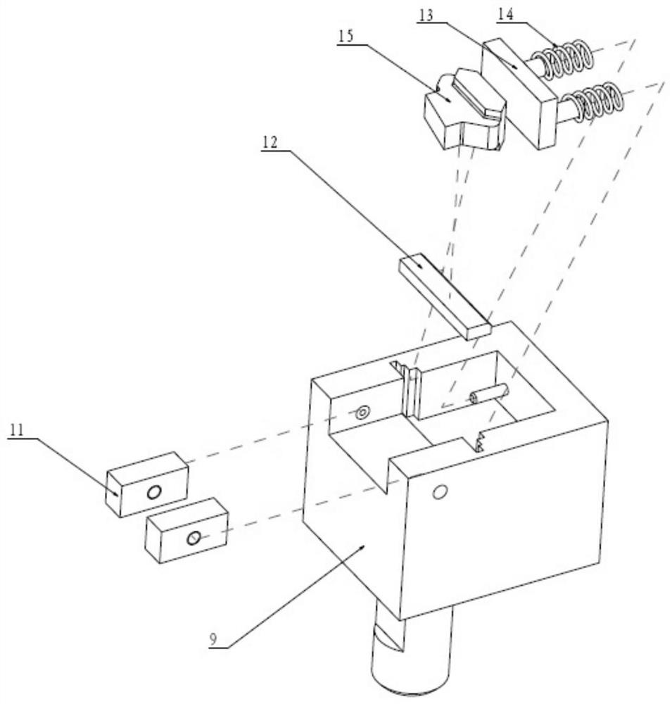
The invention relates to the technical field of gas compressor part machining equipment, in particular to a self-locking machining device for a gas compressor rotor blade locking block. The gas compressor rotor blade locking block can be fixed in a blade locking block clamp, an extrusion space is reserved, a threaded part of the locking block is plastically deformed through an extrusion rod assembly, therefore, the specified self-locking torque requirement is met, and a self-locking function is achieved. In addition, the unique blade locking block clamp is adopted, after clamping and positioning assemblies and cushion blocks of different specifications are manufactured, the clamping requirement for locking blocks can be met by installing the different clamping and positioning assemblies and the cushion blocks according to the locking blocks of different sizes and specifications, and the technical problem that self-locking machining devices of different specifications need to be manufactured in a targeted mode according to the locking blocks of different sizes and specifications is solved.

Description

technical field [0001] The invention relates to the technical field of compressor parts processing equipment, in particular to a self-locking processing device for a compressor rotor blade lock block. Background technique [0002] At present, part of the rotor blades of the compressor are installed in the corresponding blade grooves of the compressor hub, and it is necessary to use lock blocks to realize the circumferential positioning of the compressor blades, so as to prevent the compressor blades from moving in the grooves and prevent the compressor rotor blades from out of the tongue and groove. The compressor rotor rotates at a high speed, and there is vibration. Under the action of various factors, the bolts on the compressor rotor blade lock block will be loosened. [0003] Therefore, the lock block of the compressor rotor blade needs to have a self-locking function to adapt to the specific working conditions of the compressor. The lock block is extruded and deforme...

Claims


Application Information

Patent Timeline
IPC IPC(8): B21D43/00B21D31/00
CPCB21D43/003B21D31/00
Inventor 许文科李辉全姜永健王爱爱
Owner 青岛中科国晟动力科技有限公司
Learn More