Express logistics packaging device

A logistics and heating device technology, applied in the direction of packaging, transportation packaging, transportation and packaging, etc., can solve the problems of irregular packaging and other problems, achieve the effect of improving efficiency, avoiding shaking and impact, and improving the efficiency of packaging

Pending Publication Date: 2021-01-29
董广伟
View PDF7 Cites 0 Cited by
  • Summary
  • Abstract
  • Description
  • Claims
  • Application Information

AI Technical Summary

Problems solved by technology

[0006] Aiming at the deficiencies of the prior art, the present invention provides a packaging device for express logistics, which solves the problem that the existing devices cannot pack the sharp corners and bumps of irregular items, and achieves the purpose of making the adhesive tape perfectly fit the express delivery , and realized the function of tightly wrapping the express delivery, effectively avoiding the shaking and impact of the goods during transportation. The tape rod is detachable, achieving the purpose of easily replacing the tape. Packing efficiency

Method used


Image

  • Express logistics packaging device
  • Express logistics packaging device
  • Express logistics packaging device

Examples


Embodiment 1

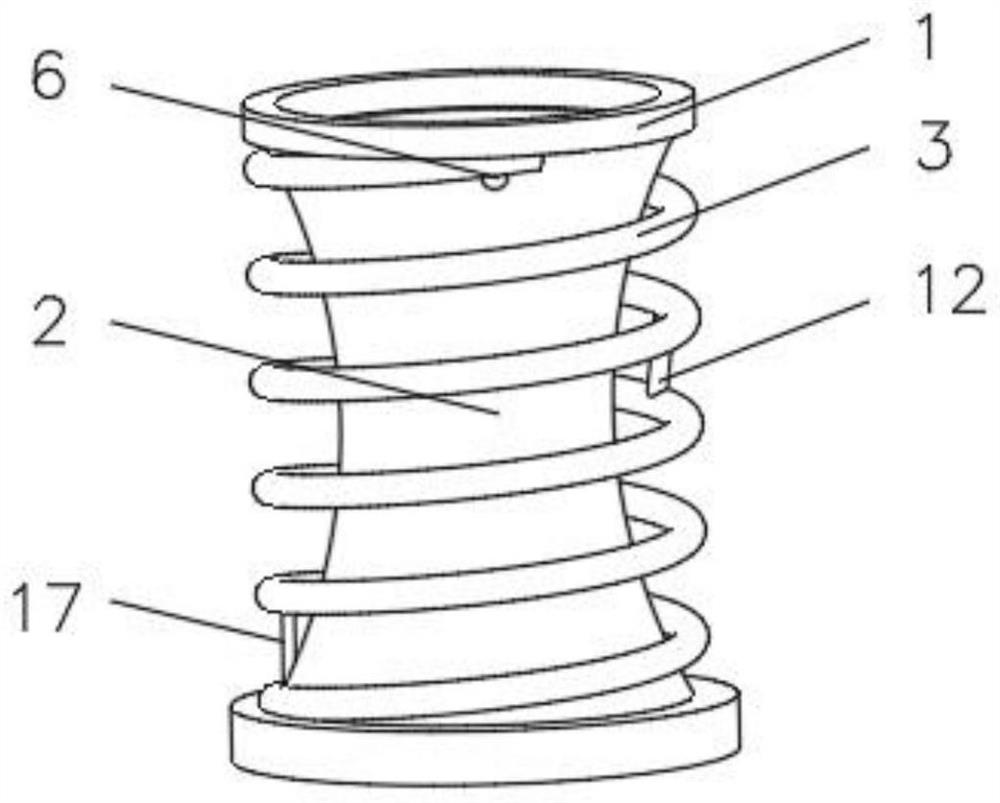
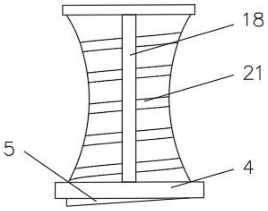
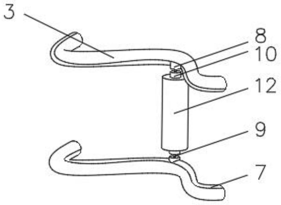
[0036] see Figure 1-4 , the present invention provides a technical solution: a packaging device for express logistics, including a top frame 1, a placement frame 2 is fixedly connected to the bottom of the top frame 1, and a spiral tube 3 is set outside the placement frame 2, and the spiral tube 3 is corrugated shape, the top end of the spiral tube 3 is fixedly connected with the top frame 1, the end of the spiral tube 3 away from the top frame 1 is fixedly connected with the bottom frame 4, one side of the spiral tube 3 is symmetrically provided with a chute 7, and the inside of the chute 7 slides A slider 8 is connected, the end of the slider 8 away from the chute 7 is fixedly connected with an elastic rope 9, the end of the elastic rope 9 away from the slider 8 is fixedly connected with a fixed rod 10, and one end of the fixed rod 10 is movably connected with a tape rod 12, The outside of the placement frame 2 is provided with a spiral groove 21 .

[0037] The bottom of t...

Embodiment 2

[0045] see Figure 1-5 , the present invention provides a technical solution: on the basis of Embodiment 1, a limit rod 14 is installed at one end of the spiral tube 3 close to the bottom frame 4, and a connecting rod 15 is symmetrically installed on one end of the limit rod 14, and the connecting rod 15 A pulley 16 is installed at an end away from the limiting rod 14 , and a cutting device 17 is installed at one side of the limiting rod 14 .

[0046] The cutting device 17 includes a fixed block 171, a rubber film 172 is installed on one side of the fixed block 171, a first spring 173 is fixedly connected to the side of the fixed block 171 close to the rubber film 172, and one end of the first spring 173 away from the fixed block 171 is fixedly connected There are blades 174 .

[0047] During use, push the stop bar 14 to make the pulley 16 slide along the chute 7, so that the position of the stop bar 14 is adjusted, and when the tape bar 12 slides down to the bottom of the sp...

Embodiment 3

[0049] see Figure 1-8 , the present invention provides a technical solution: on the basis of Embodiment 2, a hollow tube 18 is installed on one side of the top frame 1, and a round hole 19 is evenly opened on one side of the hollow tube 18 close to the position of the spiral tube 3, and the hollow tube The inside of 18 is equipped with heating device 20 .

[0050] The heating device 20 includes an inner frame 201. The top of the inner frame 201 is connected to the hollow pipe 18. One side of the inner frame 201 is communicated with a blowing pipe 202. The blowing pipe 202 extends to the outside of the round hole 19. The inner top of the inner frame 201 is installed with Fan blade 203, one end of fan blade 203 is fixedly connected with rotating rod 204, the end of rotating rod 204 away from fan blade 203 is equipped with motor 205, the output shaft of motor 205 is connected with rotating rod 204, and the inner wall of blowing pipe 202 is fixedly connected with A bracket 206, ...


PUM


Abstract

The invention discloses an express logistics packaging device. The express logistics packaging device comprises a top frame, wherein the bottom of the top frame is fixedly connected with a placing frame; a spiral pipe is arranged outside the placing frame in a sleeving mode; the spiral pipe is in a corrugated shape; one end of the top of the spiral pipe is fixedly connected with the top frame; oneend, far away from the top frame, of the spiral pipe is fixedly connected with a bottom frame; sliding grooves are symmetrically formed in one side of the spiral pipe; sliding blocks are connected into the sliding grooves in a sliding mode; one end, far away from the sliding grooves, of each sliding block is fixedly connected with an elastic rope; one end, far away from the sliding blocks, of each elastic rope is fixedly connected with a fixing rod; one end of each fixing rod is movably connected with an adhesive tape rod; a limiting rod is arranged at the position, close to the bottom frame,of one end of the spiral pipe; and connecting rods are symmetrically arranged at one end of the limiting rod. The invention relates to the technical field of logistics packaging. According to the express logistics packaging device, the function of tightly wrapping the express is achieved, and the packaging efficiency is improved.

Description

technical field [0001] The invention relates to the technical field of logistics packaging, in particular to an express logistics packaging device. Background technique [0002] At present, in view of the rapid development of the express logistics industry, there are higher requirements for the way and efficiency of express packaging. However, the express packaging work of express service points is basically manual operation, so the efficiency is slow. Some of the packaging devices in the market are too large and occupy a large area, and some are cumbersome and inconvenient to operate. limited. [0003] For example, the invention of Chinese patent CN108583966A proposes a tape wrapping device for express packaging, which includes a clamping device, a rotating packaging device and a control device, and both the clamping device and the rotating packaging device are electrically connected to the control device. The device includes a supporting platform for supporting the packa...

Claims


Application Information

Patent Timeline
Patent Type & Authority Applications(China)
IPC IPC(8): B65B67/12B65B51/06
CPCB65B51/06B65B67/1238B65B2067/1283
Inventor 董广伟
Owner 董广伟
Why Eureka
Try Eureka