Brick paving equipment for municipal engineering

A brick laying equipment and engineering technology, applied in roads, road repairs, roads, etc., can solve the problems of inconvenient compaction, poor laying effect, poor brick laying effect, etc., to achieve good laying effect, avoid gaps, and sturdy use The effect of longevity

Inactive Publication Date: 2021-01-29
岑颖明
View PDF6 Cites 5 Cited by
  • Summary
  • Abstract
  • Description
  • Claims
  • Application Information

AI Technical Summary

Problems solved by technology

[0004] The purpose of the present invention is to provide a kind of brick-laying equipment for municipal engineering, to solve the problem that the existing brick-laying equipment for municipal engineering proposed in the above-mentioned background technology is not smooth when the road surface is uneven before the bricks are laid. It is convenient for compaction treatment, and the compaction after laying can make the bricks fully contact with the cement, but the gap between the bricks is large, so the uneven road surface will cause the bricks to tilt after laying, the effect of laying bricks is poor, and the gaps in the road surface are large , the problem of poor laying effect

Method used


Image

  • Brick paving equipment for municipal engineering
  • Brick paving equipment for municipal engineering
  • Brick paving equipment for municipal engineering

Examples


Embodiment 1

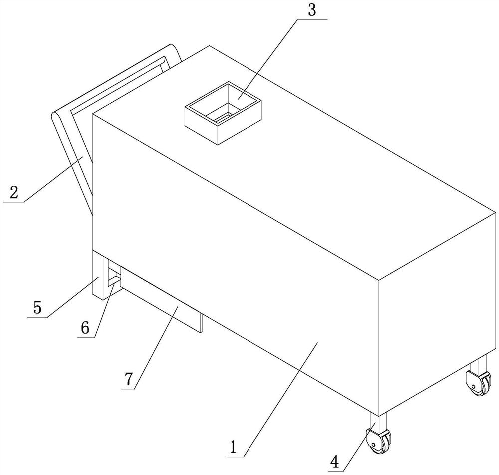
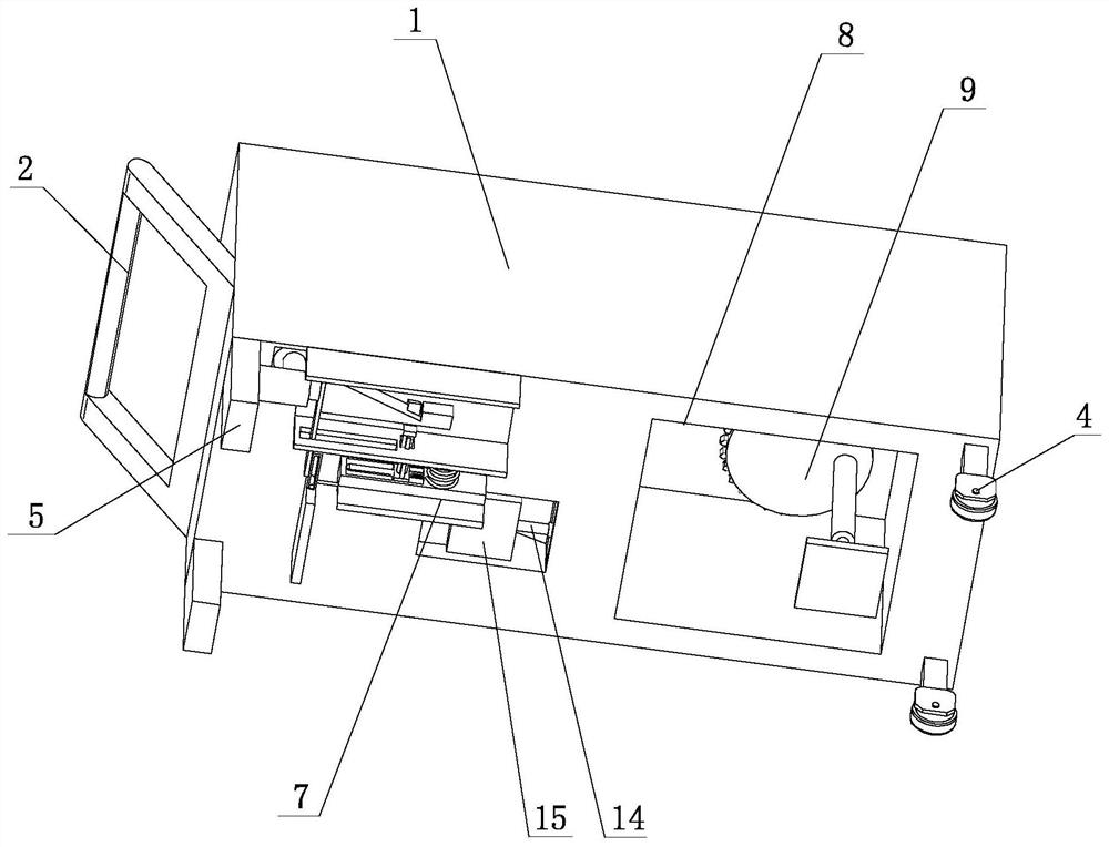
[0030] see Figure 1-Figure 2 , Figure 5-Figure 6, the present invention provides a technical solution: a kind of brick laying equipment for municipal engineering, including equipment body 1, auxiliary leveling device 7 and comprehensive compacting device 9, one side outer wall of equipment body 1 is fixedly connected with push handle 2, equipment The top outer wall of the main body 1 is fixedly equipped with a hopper 3, the bottom outer wall of the equipment body 1 is fixedly connected with two rollers 4, and the bottom outer wall of the equipment body 1 away from the side of the rollers 4 is fixedly connected with two support columns 5, the support column 5 A limit chute 6 is provided on one side of the device body 1, an auxiliary flattening device 7 is fixedly connected to the bottom of the device body 1, and an accommodation groove 8 is provided at the bottom of the equipment body 1, and a comprehensive compacting device 9 is fixedly connected to the inner wall of the acc...

Embodiment 2

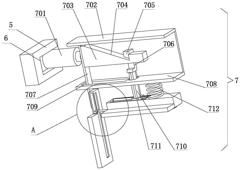
[0033] like Figure 1-4 As shown, on the basis of Embodiment 1, the present invention provides a technical solution downwards: the auxiliary flattening device 7 includes a driving cylinder 701, the bottom outer wall of the equipment body 1 is fixedly connected with a bonding plate, and the bottom outer wall of the equipment body 1 passes through The bonding plate is fixedly connected with a fixed plate 1 702, one side of the driving cylinder 701 is fixedly connected with a moving block 703, one side of the moving block 703 is provided with a wedge-shaped groove 704, and one side of the moving block 703 is slidingly connected with a moving column 705, and the moving column One side of 705 is provided with a trapezoidal groove 706, the side of the moving block 703 close to the driving cylinder 701 is fixedly connected with a connecting plate 707, the bottom of the device body 1 is fixedly connected with a fixed plate 2 708 through a laminating plate, and the inside of the fixed p...

Embodiment 3

[0036] like Figure 1-7 As shown, on the basis of Embodiment 1 and Embodiment 2, the present invention provides a technical solution downwards: the comprehensive compaction device 9 includes a drive motor 901, and the bottom of the drive motor 901 is connected with a motor shaft 902 for rotation, and the motor shaft 902 The outer wall of the motor shaft 902 is fixedly connected with a rotating plate 903, the bottom of the motor shaft 902 is fixedly connected with a driving gear 904, the top inner wall of the receiving tank 8 is fixedly connected with a rotating seat 905, and the bottom of the rotating seat 905 is rotatably connected with a rotating rod 906. The bottom is fixedly connected with a rotating gear 907, the top of the rotating gear 907 is fixedly connected with a rotating column 908, the bottom of the rotating gear 907 is fixedly connected with a compacting cylinder 909, and the bottom of the compacting cylinder 909 is fixedly connected with a compacting plate 910. ...


PUM


Abstract

The brick paving equipment for municipal engineering. The equipment comprises an equipment body, an auxiliary bulldozing device and a comprehensive compaction device, wherein a push handle is fixedlyconnected to the outer wall of one side of the equipment body, a feeding hopper is fixedly installed on the outer wall of the top of the equipment body, and two rolling wheels are fixedly connected tothe outer wall of the bottom of the equipment body. Through the arrangement of the auxiliary bulldozing device, when two hydraulic cylinders are started at the same time, a driving air cylinder and an attaching plate move downwards at the same time, and when the auxiliary bulldozing device moves to one side of a laid brick, the driving air cylinder is started, a moving block and a connecting plate move rightwards at the same time, and the inner wall of a wedge-shaped groove slides on the inner wall of a trapezoidal groove; when the connecting plate moves, the second push plate is driven to move towards the side close to the first push plate, the first push plate and the second push plate gradually get close to each other to conduct bulldozing treatment on the newly laid bricks, the distance between the bricks and the last brick is made to be closer, gaps are small, and loosening between the bricks is avoided; the laying effect is better.

Description

technical field [0001] The invention belongs to the technical field of brick-laying equipment, in particular to a brick-laying equipment for municipal engineering. Background technique [0002] A sidewalk is a section of a road dedicated to pedestrians that is separated by curbs or guardrails and other similar facilities. Sidewalks are very common in cities, and there are usually sidewalks next to the streets. In some places, the sidewalk and the motorway are separated by grass or trees. There are fewer sidewalks in the country. Laws in many parts of developed countries require that all inconvenient facilities be removed from the sidewalk, so the sidewalk is specially lowered to the same level as the road where the road is crossed, so that wheelchairs can cross the road. Bricks and stones are also commonly used materials. Generally, the foundation of sidewalks is not as strong as that of roads. Some are built on the original stone or mud roads. Laying bricks is conducive ...

Claims


Application Information

Patent Timeline
Patent Type & Authority Applications(China)
IPC IPC(8): E01C19/52
CPCE01C19/52
Inventor 岑颖明
Owner 岑颖明
Why Eureka
Try Eureka