[0027]The technical solutions in the embodiments of the present invention will be clearly and completely described below in conjunction with the accompanying drawings in the embodiments of the present invention. Obviously, the described embodiments are only a part of the embodiments of the present invention, rather than all the embodiments. Based on the embodiments of the present invention, all other embodiments obtained by those of ordinary skill in the art without creative work shall fall within the protection scope of the present invention.
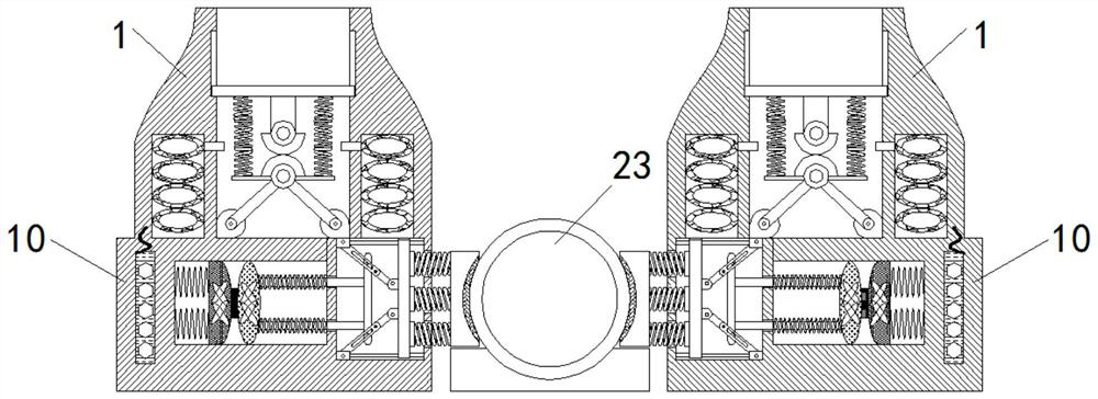
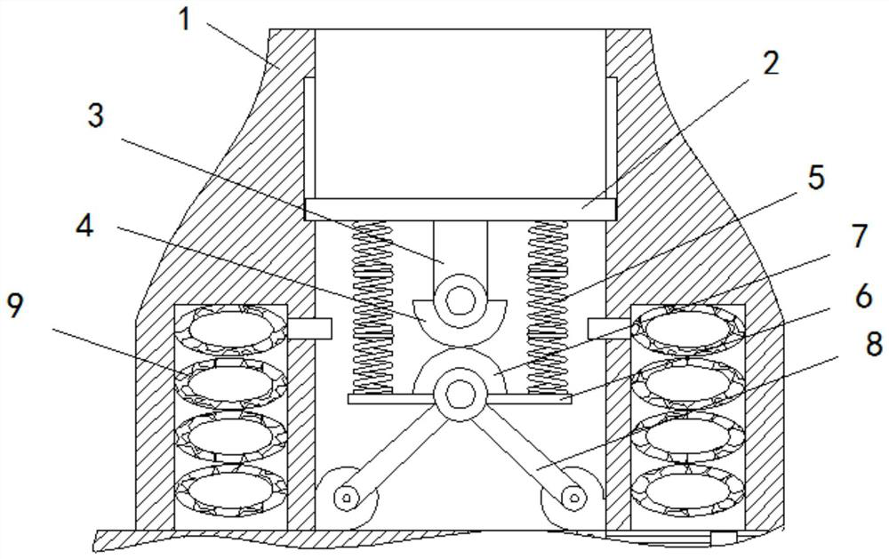
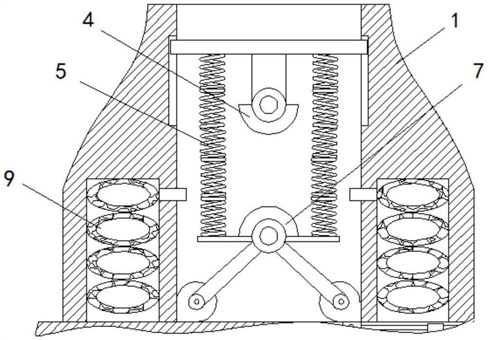
[0028]SeeFigure 1-5, A stainless steel submersible pump automatic fixing protection device, comprising a water inlet pipe 1, the inner wall of the water inlet pipe 1 is slidably connected with a piston plate 2, the bottom end of the piston plate 2 is fixedly installed with a first mandrel 3, the bottom of the first mandrel 3 A first conductive block 4 is fixedly installed at the end, a first spring 5 is fixedly installed at the bottom end of the piston plate 2, a bottom plate 6 is fixedly connected to the other end of the first spring 5, and a second conductive block 7 is fixedly installed on the upper surface of the bottom plate 6 , The bottom end of the bottom plate 6 is fixedly connected with a support rod 8, the other end of the support rod 8 is fixedly connected with the inner side wall of the water inlet pipe 1, and airbags 9 are fixedly installed inside the inner walls of both sides of the water inlet pipe 1;
[0029]A fixed box 10 is fixedly installed at the bottom end of the water inlet pipe 1, an electromagnet 11 is fixedly installed on the left inner wall of the fixed box 10, a second spring 12 is fixedly installed on the left inner wall of the fixed box 10, and the other end of the second spring 12 is fixed. A first magnetic block 13 is installed, a second magnetic block 14 is installed on the first magnetic block 13, a contact button 25 is fixedly installed on the left end of the second magnetic block 14, and a second ejector rod is fixedly installed on the right end of the second magnetic block 14 15. The outer wall of the second mandrel 15 is sleeved with a third spring 24, the other end of the second mandrel 15 is fixedly installed with a push rod 16, and both ends of the push rod 16 are fixedly installed with a protruding head 17. A first swing rod 18 is slidably connected to the outer wall, one end of the first swing rod 18 is movably connected with the inner wall of the fixed box 10, and the other end of the first swing rod 18 is movably connected with a second swing rod 19, and the other end of the second swing rod 19 A push plate 20 is movably connected to one end, a fourth spring 21 is fixedly mounted on the other side of the push plate 20, a fan-shaped splint 22 is fixedly mounted on the other end of the fourth spring 21, and a submersible pump body 23 is fixedly mounted on the inner side of the fan-shaped splint 22.
[0030]The inner wall of the water inlet pipe 1 is provided with an annular slide groove, the size of the piston plate 2 matches the size of the annular slide groove, there are two first springs 5, and the first springs 5 are respectively distributed on two sides of the first ejector rod 3. Side, the first conductive block 4 and the second conductive block 7 are in contact with each other. The shapes of the first conductive block 4 and the second conductive block 7 are semi-cylindrical shapes, and the bottom end of the support rod 8 is fixedly connected to the inner side wall of the water inlet pipe 1. The air bag 9 is fixedly connected with an air inlet pipe at the air inlet end, and the air inlet pipe is connected to the water inlet pipe 1. There are two second springs 12, and the second springs 12 are respectively released on the upper and lower ends of the left side wall of the first magnetic block 13 , The second spring 12 is a compression spring, the first magnetic block 13 and the second magnetic block 14 are made of rubidium magnet material, the magnetism of the right end of the electromagnet 11 is the same as that of the left end of the first magnetic block 13, and the right end of the first magnetic block 13 The magnetism is opposite to that of the left end of the second magnet block 14. One end of the third spring 24 is fixedly connected to the second magnet block 14, and the other end of the third spring 24 is fixedly connected to the inner wall of the fixed box 10. On the inner wall of the fixed box 10, Slide bars are fixedly installed at the lower ends, and the push plate 20 is slidably connected to the slide bar. The other side of the push plate 20 is fixedly installed with a limit rod located inside the fourth spring 21, the first conductive block 4, the second conductive block 7, The electromagnet 11 is electrically connected with an external power source, and the contact button 25 is electrically connected with a signal light.
[0031]Working principle: When the present invention is used, the submersible pump body 23 and the fixing device are put into the water tank where the submersible pump body 23 works, and the submersible pump body 23 is placed in the middle of the fixing device. When water is put in the water tank, the water enters the inlet pipe In 1, under the action of water pressure, the water pressure squeezes the piston plate 2, the first spring 5 is compressed, the air at the bottom of the piston plate 2 enters the airbag 9 and the airbag 9 expands, the first conductive block 4 and the second conductive block 7 The contact electromagnet 11 is energized, the electromagnet 11 and the first magnetic block 13 repel and stretch the second spring 12. The first magnetic block 13 and the second magnetic block 14 are attracted, and the first magnetic block 13 and the second magnetic block 14 The contact button 25 fixed on the upper part is in contact, and the contact button 25 controls the signal light to light up, indicating that there is water in the water tank and the submersible pump body 23 can work;
[0032]The repulsion between the electromagnet 11 and the first magnetic block 13 drives the first magnetic block 13 to move to the right. The first magnetic block 13 pushes the second push rod 15 to the right through the second magnetic block 14, and the second push rod 15 passes the push rod. 16 Pushes the convex head 17 to move to the right. The convex head 17 slides in the sliding groove in the first pendulum rod 18. The convex head 17 drives the second pendulum rod 19 to move to the right through the first pendulum rod 18, and the second pendulum rod 19 squeezes The push plate 20 drives the push plate 20 to move to the right. The push plate 20 drives the fan-shaped splint 22 through the fourth spring 21 to squeeze the submersible pump body 23 through the fan-shaped splint 22 to complete the fixation of the submersible pump body 23, so that it works more smoothly;
[0033]When the water inside the water tank is almost exhausted, the water pressure drops and the piston plate 2 rises, the gas in the airbag 9 is discharged, the first conductive block 4 is separated from the second conductive block 7, and the repulsive force of the electromagnet 11 and the first magnetic block 13 is eliminated , The second spring 12 drives the first magnetic block 13 to contract. The first magnetic block 13 is separated from the contact button 25. The contact button 25 controls the signal light to go out, indicating that the water in the water tank is almost exhausted and needs to be filled. The submersible pump body 23 can The work stops and the staff needs to add water to the water tank.
[0034]It should be noted that in this article, relational terms such as first and second are only used to distinguish one entity or operation from another entity or operation, and do not necessarily require or imply one of these entities or operations. There is any such actual relationship or order between. Moreover, the terms "include", "include" or any other variants thereof are intended to cover non-exclusive inclusion, so that a process, method, article or device including a series of elements not only includes those elements, but also includes those that are not explicitly listed Other elements of, or also include elements inherent to this process, method, article or equipment. If there are no more restrictions, the element defined by the sentence "including a..." does not exclude the existence of other same elements in the process, method, article, or equipment that includes the element.
[0035]Although the embodiments of the present invention have been shown and described, those of ordinary skill in the art can understand that various changes, modifications, and substitutions can be made to these embodiments without departing from the principle and spirit of the present invention. And variations, the scope of the present invention is defined by the appended claims and their equivalents.