Dust removal and haze reduction spray fan
A spray fan and haze reduction technology, which is applied in mechanical equipment, machines/engines, liquid fuel engines, etc., can solve the problems of poor use effect and achieve the effect of reducing noise
- Summary
- Abstract
- Description
- Claims
- Application Information
AI Technical Summary
Problems solved by technology
Method used
Image

Examples
Embodiment 1
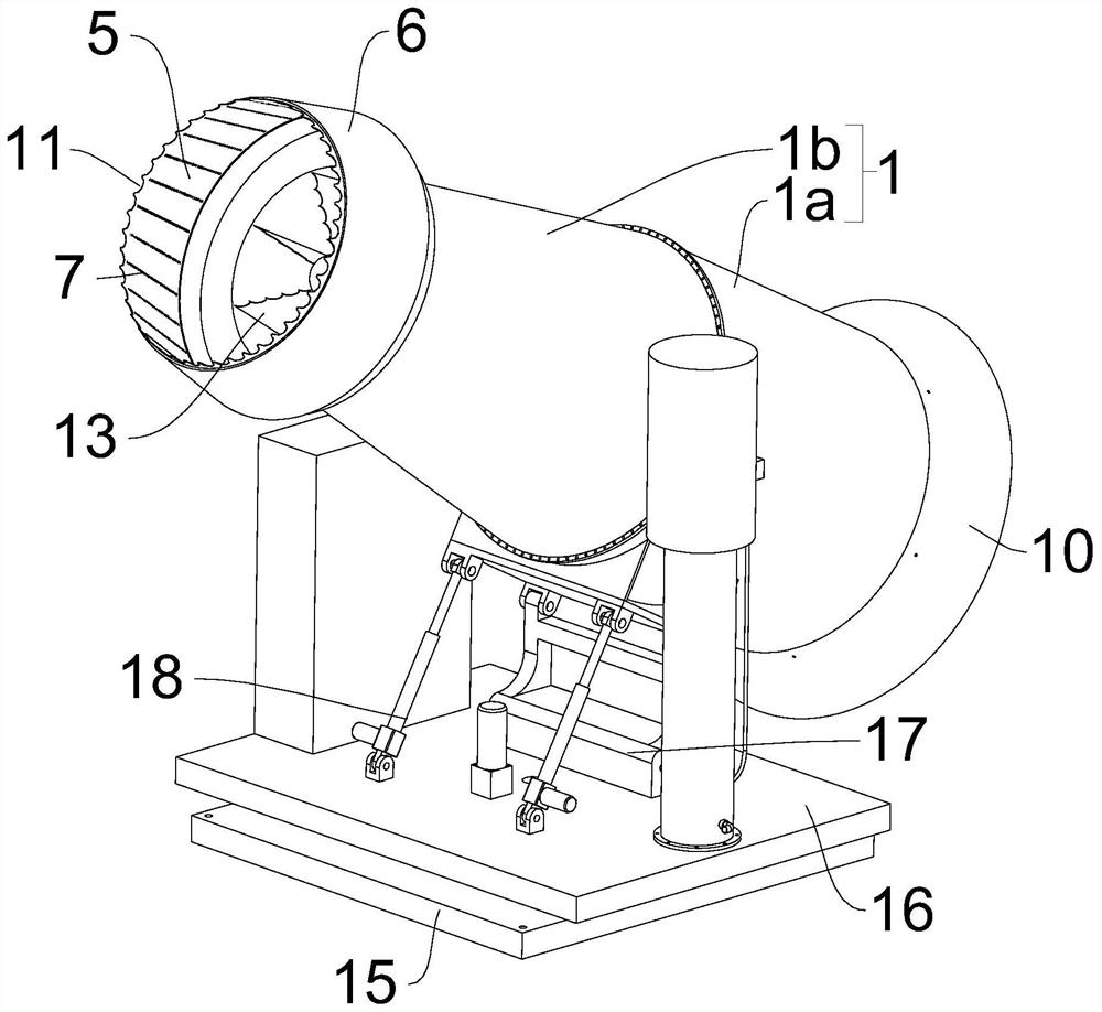
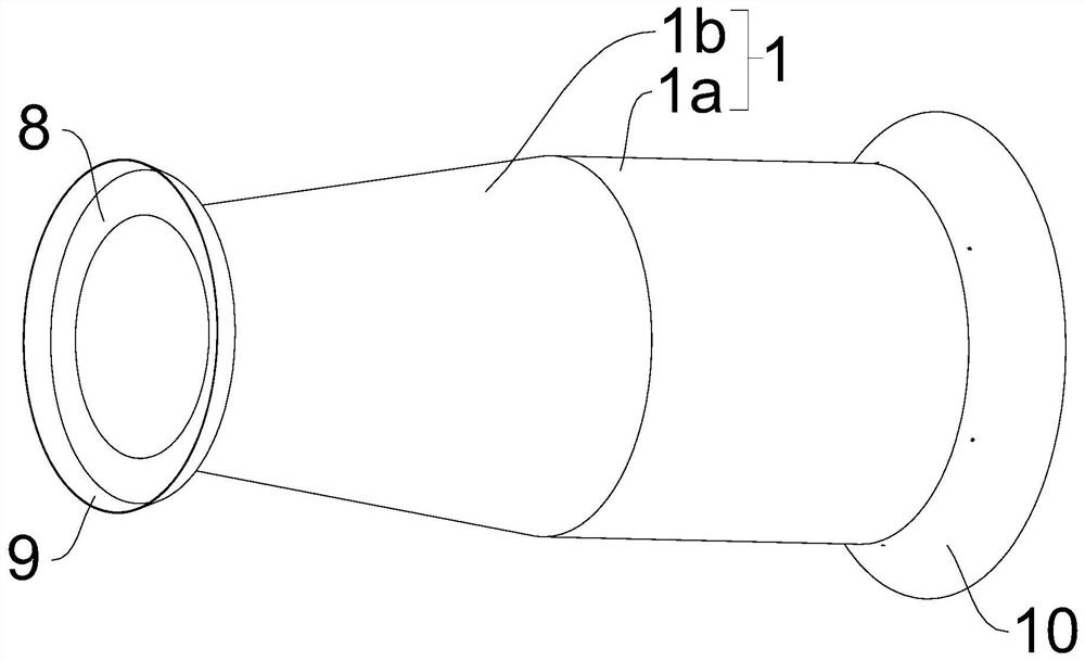
[0048] A new type of dust removal and haze reduction spray fan, such as Figure 1 to Figure 6 As shown, it includes a spray canister 1 with adjustable horizontal angle and elevation angle, a spray motor 2 arranged in the spray canister 1, a spray vane 3 arranged on the spray canister 2, and a spray canister set on the side of the spray canister 1. The water inlet 4 on the wall, the water inlet 4 is located between the spray blade 3 and the top of the spray tube 1, and the top of the spray tube 1 is provided with a sound-absorbing interior with a diameter larger than the top diameter of the spray tube 1 Tube 5 and the sound-absorbing outer cylinder 6 located outside the sound-absorbing inner cylinder 5, the axes of the spray tube 1, the sound-absorbing inner cylinder 5 and the sound-absorbing outer cylinder 6 are all collinear, and the sound-absorbing outer cylinder 6 and the There is a set distance between the sound-absorbing inner cylinders 5, which is preferably 1.5cm in thi...
Embodiment 2
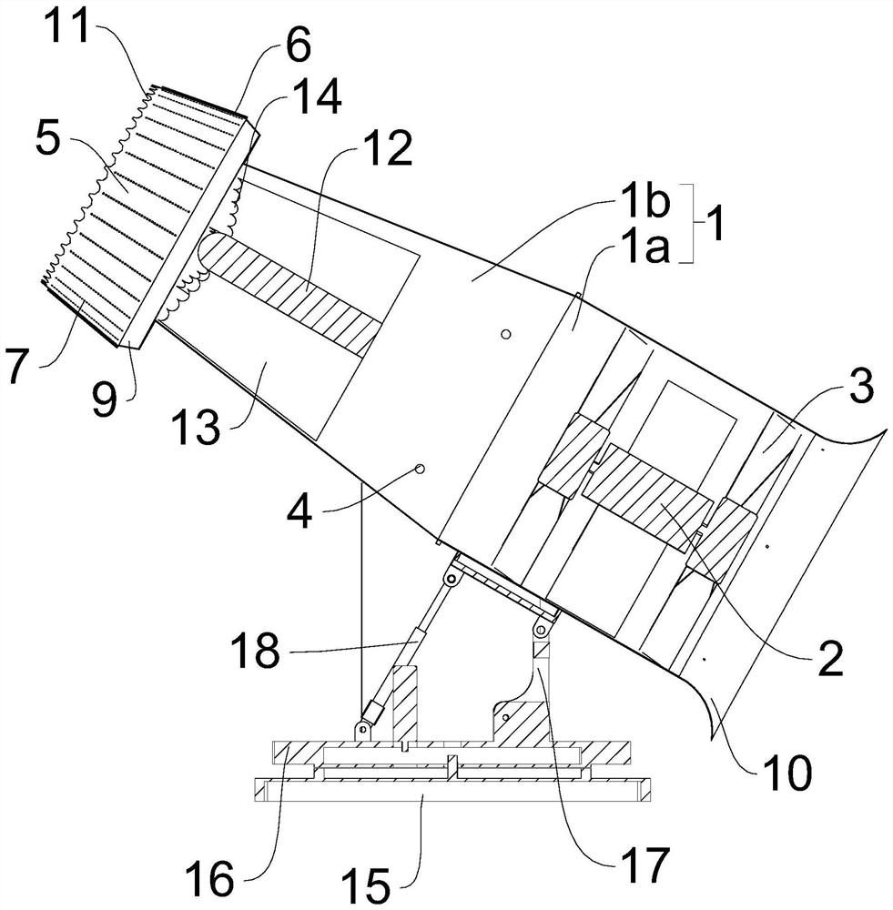
[0062] A new type of dust removal and haze reduction spray fan, such as Figure 7 to Figure 15 As shown, the difference from Embodiment 1 is that the structure for driving the spray tube 1 to swing in pitch angle and horizontal direction also includes:
[0063]The fixed plate 19 and the rotating plate 20 connected to the top of the fixed plate 19 for horizontal rotation, two support arms 21 are symmetrically arranged on both sides of the rotating plate 20, and the tops of the two support arms 21 are horizontally provided with rotating Rod 22 (there is a reinforcing ring on the outer wall of the spray tube 1, which can improve the strength of the structure of the spray tube 1 and prevent it from being deformed), and the two rotating rods 22 are respectively connected to the two sides of the spray tube 1, two The middle part of the space between the rotating rods 22 is the center of rotation;
[0064] An arc-shaped drive member 23, the position of the drive member 23 is fixed, ...
PUM
 Abstract
Description
Claims
Application Information